



How to Install a Wall Indicator Post: A Professional Step-by-Step Guide
What if a wall indicator post is firmly mounted but shows the wrong valve status? A mismatch between the post, valve, and wall conditions can make an installation look complete while leaving the open-or-shut indication unreliable. Learning how to install a wall indicator post means verifying the fit and the indication together, not just fastening hardware in place.
It makes sense to be cautious. These components help identify and operate a fire protection control valve, and product instructions or code references may differ by model and project. This guide explains how to prepare the opening, valve, and post; follow a safe installation sequence; and check that the displayed status corresponds to the valve’s actual position. It also covers code considerations to review against project documents and locally adopted requirements. Use the exact manufacturer instructions for model-specific dimensions and adjustments, and involve qualified installation assistance when the work or verification calls for it. The goal is a secure fit, a clear indication, and no guesswork about valve status.
Key Takeaways
- Match the post to the identified valve, wall opening, approved plans, and exact manufacturer instructions before work begins.
- Compare configurations by valve location, wall conditions, adjustment method, and visibility to determine what the approved design calls for.
- Use a safe, verifiable sequence for how to install a wall indicator post, following project procedures for authorization and system isolation.
- Check that the post’s indication corresponds to the valve’s actual position using the manufacturer’s procedure and approved acceptance process.
- Document the installed model, adjustment, instructions, test results, and any corrective work to support clear follow-up.
What a Wall Indicator Post Does, and Why Correct Installation Matters
A control valve can be concealed inside a building wall, making its position difficult to see from outside. A wall indicator post provides an external indication and an operating point for that valve, helping authorized personnel identify and operate it as intended. It is one component within the broader context of fire protection systems, where clear access to control points supports system operation and maintenance.
A wall indicator post is an assembly that displays and operates a concealed control valve; it is not the valve itself. The valve controls water flow. The post connects to the valve through an operating mechanism and communicates its position at the wall. Other indicator-post arrangements may be designed for valves in different locations, so a wall-mounted assembly should not be treated as interchangeable with every freestanding or vertical configuration.
The assembly’s exact design, fit, and adjustment method depend on its manufacturer and model. That’s why how to install a wall indicator post can’t be reduced to a universal set of dimensions or fastening steps. The approved project documents and exact installation instructions determine what applies to the specific assembly.
How the wall post communicates valve position
The post’s operating mechanism links its external indication to the valve’s position. Depending on the model, the instructions specify how the indicator should read when the valve is open or shut, and how the mechanism should be adjusted. Don’t assume that all posts use the same target, wording, or adjustment procedure.
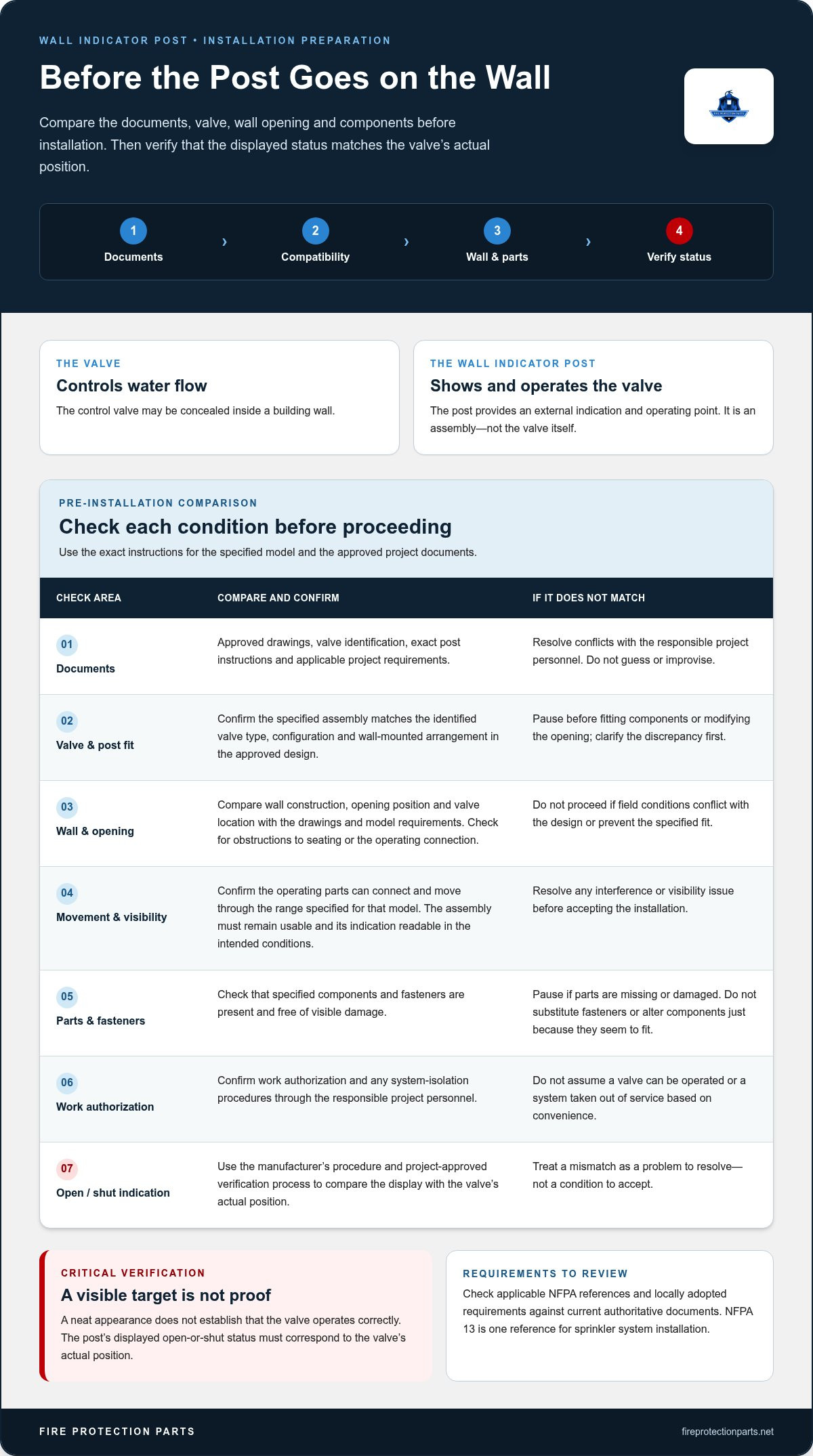
A visible target is not proof by itself that the valve operates correctly. Check the indication against the valve’s actual position using the manufacturer’s procedure and the project-approved verification process. If the display and valve position don’t agree, treat the mismatch as a problem to resolve, not a condition to accept.
Why installation accuracy is a life-safety issue
Incorrect alignment or adjustment can make the post indicate a position that doesn’t match the valve. That can mislead someone relying on the external display during system operation or maintenance. A neat appearance isn’t enough; the assembly must fit the valve and wall conditions and indicate position as intended.
Follow the approved project documents and exact manufacturer instructions throughout installation and verification. Where the work involves fire protection system installation or acceptance, qualified fire protection personnel should carry out or oversee the steps within their responsibility. If instructions conflict with project documents, don’t guess or improvise. Resolve the discrepancy through the project’s responsible personnel before proceeding.
Prepare the Valve, Wall Opening, and Wall Indicator Post
Preparation starts with the approved project documents, not the opening in the wall. Identify the control valve and confirm the specified wall indicator post model. Then locate the manufacturer’s installation instructions for that exact assembly. Similar-looking posts may have different connection details, adjustment ranges, or fastening requirements. Generic dimensions aren’t a safe substitute for model-specific information.
Before work begins, compare the documents and equipment. Confirm that the post is intended for the identified valve and the wall-mounted arrangement shown in the approved design. Review applicable NFPA references and locally adopted requirements using current authoritative documents. The NFPA 13 Standard for the Installation of Sprinkler Systems is one reference for sprinkler system installation; determine which standards and project requirements apply to the specific assembly.
Confirm compatibility and project requirements
Check the valve identification against the approved drawings and the post instructions. Verify that the specified assembly matches the valve type and configuration, and that the instructions address the installation conditions at the site. If drawings, instructions, or field conditions conflict, stop and resolve the discrepancy with the responsible project personnel before modifying the opening or fitting components.
Also confirm the required work authorization and any system-isolation procedures through the project’s responsible personnel. Don’t infer that a valve can be operated or a system taken out of service based on convenience. The work plan must control those decisions.
Inspect the opening and installation area
Compare the wall construction, opening position, and valve location with the approved drawings and manufacturer requirements. Check for obstructions that could prevent the post from seating correctly or interfere with the operating connection. Confirm that the operating parts can connect and move through the range specified for that model. Access and visibility matter too: the installed assembly must remain usable, and its indication must be readable under the project’s intended conditions.
Before installation, inspect the post components and specified fasteners. Make sure the parts called for by the instructions are present and free of visible damage. Don’t substitute a fastener or alter a component simply because it seems to fit. If a part is missing, damaged, or inconsistent with the instructions, pause and resolve the issue before proceeding.
- Documents: Approved drawings, valve identification, exact post instructions, and applicable project requirements.
- Fit: Wall construction, opening location, valve position, and unobstructed movement of connected operating parts.
- Condition: Required post components and fasteners present and undamaged.
- Limits: Dimensions, clearances, and adjustments taken only from the exact model’s instructions and approved documents.
This preparation makes how to install a wall indicator post a controlled, project-specific task rather than a trial fit. For component questions as you organize the work, fire protection parts and technical support can be a practical resource.
Choose the Right Wall Indicator Post Configuration for the Installation
Configuration follows the valve location and approved design. A wall-mounted arrangement is generally considered when the control valve is positioned to be operated and indicated through a wall. Other indicator-post arrangements serve different installation layouts. Similar purpose does not mean interchangeable fit: the valve connection, mounting conditions, and adjustment method can differ by assembly.
Start with the project drawings and manufacturer documentation for the exact assembly under consideration. They establish whether the arrangement suits the valve and site. General orientation can guide the comparison, but dimensions, clearances, adjustment provisions, and operating limits must come from the approved documents and model-specific instructions. For broader workplace context, OSHA provides fire safety information; it does not replace project-specific fit and installation requirements.
When a wall-mounted arrangement may fit the project
A wall-mounted post may be appropriate when the approved design places the valve behind a wall and calls for its position and operation to be accessed from the wall’s exterior. Confirm the arrangement against the drawings, valve identification, and post instructions. Wall construction, opening location, operating access, and indicator visibility all affect suitability. Don’t select a configuration based on appearance alone.
What to compare before committing to a configuration
Use this comparison to identify what needs to be verified. It is orientation, not a substitute for model-specific requirements. For any proposed arrangement, resolve unanswered fit or adjustment questions against the exact manufacturer documentation before proceeding.
| Comparison point | Wall-mounted arrangement | Other indicator-post arrangement |
|---|---|---|
| Wall conditions | Check wall construction, opening location, and mounting requirements against the drawings and instructions. | Check the site conditions and mounting arrangement specified for that assembly. |
| Valve compatibility | Verify that the assembly is intended for the identified valve and approved configuration. | Verify compatibility independently; don’t assume it matches a wall-mounted assembly. |
| Adjustment method | Use the exact manufacturer procedure; adjustment provisions and limits vary by model. | Consult that model’s instructions; don’t transfer adjustment assumptions from another post. |
| Access and visibility | Confirm the operating point is accessible and the indication can be seen from the intended location. | Assess access and visibility for the location shown in the approved design. |
The table helps organize the decision, but the approved plans and exact product documentation control. If they identify a wall-mounted assembly, don’t substitute another configuration because it appears easier to fit. If field conditions differ from the drawings, pause and have the responsible project personnel resolve the discrepancy before installation. This keeps configuration selection tied to the actual valve, wall, and approved design, rather than guesswork.
How to Install a Wall Indicator Post: A Safe, Verifiable Sequence
The exact model instructions govern every dimension and adjustment. Use this sequence as a framework only. The manufacturer’s instructions, approved project plans, and responsible project procedures take precedence. Installation and functional checks should be completed by qualified fire protection personnel within their assigned responsibilities.
- Confirm authorization and system status. Follow the project’s procedures for work authorization and system isolation. The responsible personnel must determine whether and how the system is isolated. Don’t operate a valve or change system status based on assumption.
- Recheck the assembly and installation location. Compare the identified valve, post model, wall opening, and approved drawings before fitting components. Confirm parts and specified hardware are present and undamaged. If the site differs from the approved design, pause and resolve the discrepancy before proceeding.
- Position the post components. Place the assembly in the orientation and position specified by the manufacturer and installation drawings. Keep the operating components aligned as directed. Don’t force parts together or compensate for a mismatch by altering the wall, valve, or assembly without approval.
- Secure the assembly. Install the specified fasteners and hardware using the manufacturer-defined method. Follow the instructions for seating and securing each component. Avoid substituting hardware or applying an assumed tightening method when the instructions specify otherwise.
- Connect the operating mechanism. Couple the post to the valve as the model instructions direct. Check that the connected parts can move through their intended range without binding. If alignment or movement is restricted, stop and correct the cause through the approved process instead of forcing the mechanism.
- Adjust the indication. Set the target or display using the exact model-specific procedure and the verified valve position. Don’t rely on a visual guess or transfer an adjustment from another model. The indication must correspond to the valve position, not simply appear centered or readable.
- Complete the authorized functional check. Operate and observe the assembly only through the project-approved procedure. Verify the valve position and displayed indication together. If they don’t agree, don’t accept the installation or return the system to its approved operating condition until the issue is resolved and the check is completed successfully.
- Restore and report status. Follow responsible project procedures for returning the system to its approved operating condition. Record the check result and any adjustment or corrective work for handover.
Work deliberately. A post that is securely fastened can still be incorrectly connected or adjusted, so completion means more than a finished-looking installation. The functional check must verify both operation and indication under the approved process.
For related fire protection components and product questions, explore fire protection parts and technical support.
Verify the Installation, Document Results, and Find Fire Protection Support
A completed installation isn’t ready for handover until its operation and indication have been checked. Use the exact manufacturer procedure and the project-approved acceptance process. The check must establish that the post operates as intended and that its display corresponds to the verified valve position. Don’t return the system to service until the responsible qualified personnel have completed the required checks and followed the project’s restoration procedures.
Use a clear post-installation verification checklist
Keep the verification controlled and traceable. Follow the authorized procedure rather than relying on appearance alone. If a check fails or a result is uncertain, record the issue and resolve it before handover or return to service.
- Assembly condition: Confirm the post is secure and installed as directed by its manufacturer.
- Visibility: Check that the indicator can be read from its intended viewing position.
- Operation: Observe valve movement through the authorized project procedure. Don’t force the mechanism or operate the system outside the approved process.
- Indication: Compare the displayed position with the valve position established during the check.
- Exceptions: Record any mismatch, obstruction, adjustment, or corrective work, then repeat the relevant verification steps as required.
For a useful handover record, document the installed post model, the manufacturer instructions used, the adjustment performed, verification results, and any corrective work. Include enough detail for the responsible project personnel to understand what was checked and whether exceptions remain. Keep the record with the project documentation according to the site’s established process.
Source related components and installation assistance
Clear records also help identify related parts needed for future work. For sourcing context, see this guide to fire protection parts and hardware for system repairs and the overview of sprinkler system components online. Component selection should remain tied to the project requirements and relevant product documentation.
Fire Protection Parts provides technical support for fire protection component questions by phone, chat, email, and in-store assistance. The company also facilitates access to Fire & Life Safety Consultants, its recommended installation partner. Installation services are arranged directly between the customer and that partner.
Knowing how to install a wall indicator post includes knowing when verification is complete and when unresolved issues must hold up handover. For component information and support, explore fire protection parts and support.
Make the Next Step a Verified One
A dependable installation starts with decisions that can be checked, not assumptions that merely seem reasonable. Before work moves forward, make sure the project team has a clear path for resolving any mismatch between the approved design, the selected assembly, and the conditions at the site. That discipline keeps the next action grounded in documented requirements.
Use this guide to prepare for a focused discussion with the responsible project personnel. Bring the valve and post details, relevant manufacturer instructions, and any questions about component compatibility or documentation. If you’re still evaluating how to install a wall indicator post, keep the exact model instructions and approved project process at the center of that planning. A methodical approach helps reduce uncertainty before it becomes rework.
Fire Protection Parts supports professional users working with fire protection components. Explore fire protection parts and technical support to find useful component resources for your work. Take the next step with clarity, and keep verification in view from planning through handover.
Frequently Asked Questions
Can I install a wall indicator post without a qualified fire protection professional?
This is life-safety system work, not a routine wall-hardware task. The installation must follow the exact manufacturer instructions, approved project documents, and applicable requirements. Who may perform the work depends on local rules and project procedures, so don’t assume one licensing rule applies everywhere. Use qualified fire protection personnel for the work and required checks. If you’re researching how to install a wall indicator post, treat this guidance as educational, not a substitute for project-specific direction.
How do I know whether a wall indicator post is compatible with my valve?
Identify the installed valve, then compare its documentation with the exact post model instructions and approved drawings. A similar appearance or broad product category doesn’t establish compatibility. Check whether the documented connection method, adjustment provisions, and wall conditions match the project assembly. For example, a post that physically fits an opening may still have an incompatible operating connection. If field conditions or documents disagree, stop and resolve the question through the project’s responsible technical authority.
What happens if the wall indicator post shows the wrong valve position?
Don’t treat the assembly as reliable until the discrepancy is checked under the authorized procedure. Confirm the valve’s actual position using the project-approved process, then follow the exact model instructions for any adjustment. Don’t guess at a correction or force the operating mechanism. Document the mismatch and corrective work. Qualified personnel should retest the assembly and resolve the issue before handover or return to service, so the displayed status isn’t accepted on appearance alone.
Do wall indicator post installation dimensions follow one standard measurement?
No single measurement should be assumed for every installation. Opening size, wall conditions, connection details, and adjustment limits depend on the post model, valve arrangement, and approved project drawings. Applicable requirements may also vary with the adopted code edition and project. Use the current manufacturer instructions and approved documents for the actual values. Don’t borrow a dimension from a different product sheet, even if the other assembly looks similar or serves the same general purpose.
Does NFPA 24 specify how every wall indicator post must be installed?
Don’t read NFPA 24 as a universal, model-by-model installation recipe. The requirements that apply depend on the adopted edition, local requirements, system design, and the post manufacturer’s instructions. Check the project’s approved requirements and authoritative current documents for the relevant provisions. Avoid relying on an isolated clause or an older reference without confirming it applies to the project. Where interpretations conflict, the responsible project technical authority should resolve them before work proceeds.
How should the post be checked after installation?
Use the project-approved procedure and exact manufacturer instructions to check that the assembly is secure, visible, and operable. Confirm that the indicator agrees with the valve position established through the authorized check. A readable target alone doesn’t demonstrate correct operation or prove the full system meets project requirements. Record the result and any exceptions. If the indication and valve position don’t match, have qualified personnel resolve the issue and repeat the required checks before handover or return to service.
Can Fire Protection Parts install a wall indicator post?
Fire Protection Parts provides technical support for fire protection component questions by phone, chat, email, and in-store assistance. The company facilitates a connection to its recommended installation partner, Fire & Life Safety Consultants. Installation services are arranged directly between the customer and the partner. For component information and support, explore Fire Protection Parts.

