

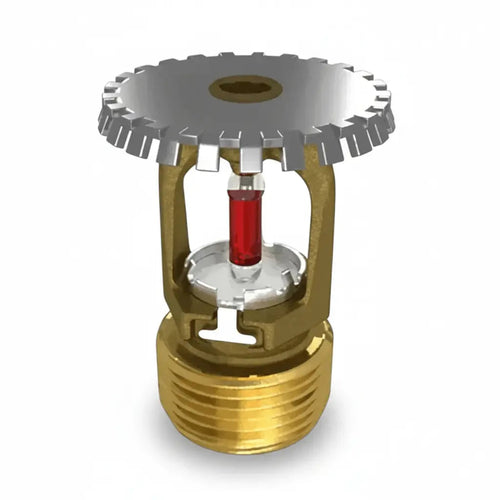


Preaction Retrofit Example for Data Center Upgrades
A water leak over active server racks can create a business interruption event long before a fire ever reaches a sprinkler operating temperature. This preaction retrofit example shows how a contractor might convert an aging wet-pipe sprinkler zone serving a data center into a double-interlock preaction system. It is an illustrative project scenario, not a substitute for a stamped design, the adopted codes, manufacturer instructions, or approval by the authority having jurisdiction (AHJ).
The objective is not simply to install a new valve. A successful preaction retrofit must coordinate sprinkler piping, water supply, detection, releasing controls, supervisory air, electrical power, inspection access, and acceptance testing. Missing one of those elements can delay turnover or create a system that does not operate as intended.
Existing Conditions and the Retrofit Objective
Consider a 12,000-square-foot data center suite in an occupied commercial building. The existing protection is a wet-pipe sprinkler system with upright sprinklers above the suspended ceiling. The building owner is adding high-value IT equipment and wants greater protection against accidental water discharge from a damaged sprinkler, broken fitting, or maintenance error.
The existing wet system is functional, but its branch lines contain water at all times. In a double-interlock preaction arrangement, the sprinkler piping is normally dry. Before water enters the system, both a detection event and a sprinkler operation or loss of supervisory air are required, depending on the listed valve arrangement and system design. This approach can reduce the chance that a single mechanical incident introduces water into the protected space.
That added protection comes with trade-offs. A preaction system introduces more components, more testing responsibilities, and more coordination between fire alarm and sprinkler disciplines. It may also add time before water reaches an operating sprinkler compared with a wet system. The design team must determine whether the application, hazard, water supply, and owner requirements support the conversion.
Preaction Retrofit Example: Scope of Work
In this example, the contractor begins with a field survey rather than assuming the existing system can be converted without changes. The survey verifies ceiling construction, hazard classification, sprinkler spacing, pipe sizes, riser room space, drain routing, available electrical power, and the condition of the existing piping.
The contractor also reviews the latest hydraulic calculation information, available water supply data, fire alarm drawings, inspection records, and any prior deficiencies. If the original documentation is incomplete, field verification becomes even more important. Existing pipe may need internal inspection, replacement, or cleaning before it is used in a dry or preaction application. Changes in pipe schedule, fittings, sprinkler characteristics, elevation, or system demand can require new hydraulic calculations.
The retrofit scope includes replacing the wet alarm valve arrangement with a listed double-interlock preaction valve assembly, installing compatible trim, and providing the air supervisory equipment required by the valve manufacturer. Depending on system size and air demand, that may include a listed air compressor, air maintenance device, pressure switches, and associated supervisory piping.
The sprinkler piping is drained and modified where necessary to support dry-pipe service. This can involve correcting pitch, adding or relocating auxiliary drains, addressing trapped sections, and replacing components not suitable for the revised system. Drainage is not a minor detail. Standing water in low points can contribute to corrosion, freeze issues where applicable, and impaired system operation.
Selecting the Valve and Releasing Components
The valve assembly must be listed for the intended preaction arrangement and installed exactly as its manufacturer requires. Contractors commonly source valve, trim, supervisory, and releasing components from established fire protection manufacturers, but brand compatibility is never an assumption. The valve trim, solenoid valve, pressure switches, releasing panel, and detection circuits must operate as a listed system.
For this project, the design calls for a listed preaction valve with electric release capability and supervisory air monitoring. The installer provides a releasing control panel compatible with the required detection logic, notification and supervisory functions, and connection method to the building fire alarm system. A dedicated releasing panel is often preferable to trying to force releasing functions through a general-purpose fire alarm control unit without confirming listed compatibility.
Electrical supervision matters throughout the assembly. The panel must monitor initiating circuits, releasing circuits, power supplies, battery capacity, and relevant supervisory conditions. The sprinkler contractor and fire alarm contractor should establish the interface responsibilities before material is ordered. A valve can be mechanically complete while still unable to pass acceptance testing because a supervision point, relay, circuit designation, or alarm connection was overlooked.
Detection Changes for Double Interlock Operation
The data center owner wants early warning and controlled preaction release, so the design team specifies automatic detection in the protected area. The final detector type and layout depend on ceiling geometry, airflow, environmental conditions, and applicable fire alarm requirements. Spot smoke detection may be appropriate in some locations, while other applications may call for alternate detection methods based on the design criteria.
In a typical double-interlock arrangement, detector activation opens the releasing path but does not by itself admit water into the sprinkler piping. A sprinkler must also operate, or the system must experience the required loss of air pressure, before the valve trips and water enters the system. The precise sequence depends on the listed equipment and design configuration.
This logic needs to be documented clearly for the owner, monitoring provider, inspection personnel, and responding fire department personnel. Confusion between an alarm condition, a supervisory condition, and a waterflow condition creates avoidable operational problems. Device labels, panel programming records, valve-room signage, and sequence-of-operation documentation should all match.
Installation Details That Affect Turnover
During the conversion, the contractor isolates the existing sprinkler zone and coordinates impairment procedures with building management. The affected area may need temporary fire watch measures or other impairment controls as required by the site and AHJ. For an active data center, work sequencing is often as critical as the material list. Planned shutdown windows, access controls, dust containment, and communication with IT operations can prevent a fire protection improvement from disrupting a critical facility.
The new valve assembly is installed with adequate working clearance for inspection, resetting, testing, and future service. The riser room must also accommodate drainage without creating a slip hazard or damaging nearby equipment. All control valves are supervised where required, identified, and left accessible.
The installer updates pipe identification and provides durable signage at the valve assembly. Signage should identify the system as preaction, explain the basic operating condition, and provide reset information consistent with the manufacturer’s instructions. A technician should not have to guess whether the system is wet, dry, single interlock, or double interlock during an emergency service call.
Testing and Documentation Before Acceptance
A preaction retrofit is not ready for turnover when the last fitting is installed. It is ready when the completed system has passed the required inspections and tests, and the owner has accurate records for ongoing service.
Testing generally includes hydrostatic and pneumatic tests as applicable, main drain verification, alarm and supervisory testing, releasing circuit testing, detector functional testing, waterflow confirmation, and a full trip test in accordance with the approved design, applicable standards, and manufacturer procedures. The team should verify the actual sequence: detection response, supervisory air condition, valve operation, water delivery, alarm transmission, and reset procedure.
The contractor should also confirm that all auxiliary drains are identified and that the owner understands their drainage schedule where required. For dry and preaction piping, overlooked low points can become a recurring maintenance issue.
Turnover documents should include approved drawings, hydraulic calculations when required, product data, valve and releasing-panel manuals, test reports, inspection records, sequence-of-operation information, and final device and valve identification. This package is valuable to the facility team, but it is equally valuable to the next inspection contractor who must service the system years later.
What This Example Teaches
The key lesson from this preaction retrofit example is that a valve replacement alone does not create a dependable preaction system. The retrofit succeeds when the mechanical and electrical portions are designed, supplied, installed, tested, and documented as one coordinated life safety system.
For contractors and facility teams, the practical starting point is a complete existing-condition survey and a material package built around listed, compatible components rather than low-cost substitutes. When the project scope is clear before ordering, the installation is easier to schedule, easier to inspect, and far less likely to leave a critical space exposed while the right parts are being located.

