



Choose a Test and Drain Valve for Your Sprinkler System
Orientation is a functional requirement, not a finishing detail. To understand how to install a test and drain valve, match its inlet and outlet to the direction of flow, position it correctly, and route discharge to a safe location. In a combination sprinkler/standpipe system, place the valve downstream of the floor control valve and connect it to a drain riser for flow testing.
Choosing the right valve also means matching the test orifice to the sprinkler system and keeping the assembly accessible for operation and maintenance. This guide explains the difference between the valve’s test and drain functions, the code requirements that affect selection and placement, and how orientation and discharge location support safe, reliable testing.
Key Takeaways
- Match the test orifice to the sprinkler system’s required flow, and choose a valve that can also serve the intended drain function.
- Plan the discharge for safe water disposal: it must go outside, to a drain that can handle the flow, or somewhere water damage won’t result.
- Keep the valve accessible and position it correctly for the system, including downstream of the floor control valve in a combination sprinkler/standpipe setup.
- Check the valve’s flow direction before installation: water enters through the inlet and leaves through the outlet.
- Understand how the handle, test port, drain path, and any pressure-relief port work together before selecting the assembly.
Draining, pressure testing, and sprinkler testing
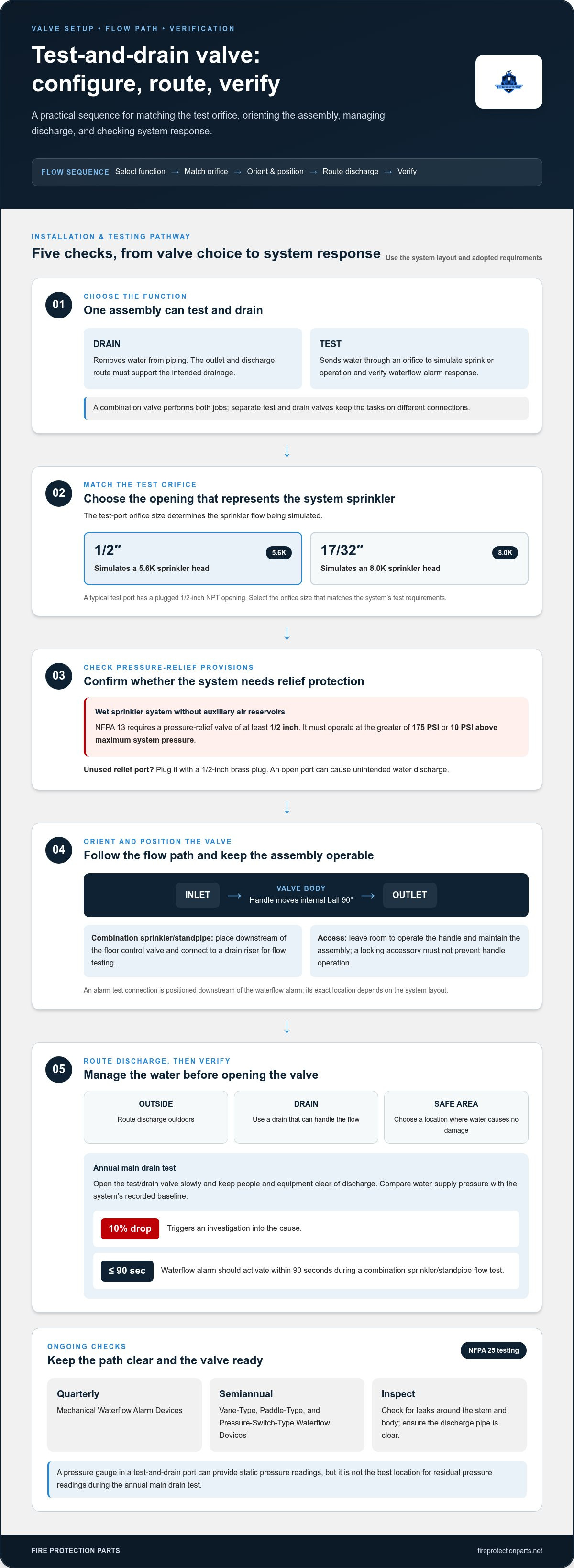
A test-and-drain valve can serve as the main drain on a wet sprinkler system or zone control assembly. Its drain function removes water; its test function sends water through an orifice to simulate sprinkler operation and verify the waterflow alarm. A typical test port has a plugged 1/2-inch NPT opening. The orifice size matters: a 1/2-inch orifice simulates a 5.6K sprinkler head, while a 17/32-inch orifice simulates an 8.0K head. Select the size that matches the system’s test requirements.
TESTanDRAIN models differ in their pressure-relief arrangements. A model without pressure relief provides test and drain functions, while a model with pressure relief includes a port for that additional component. NFPA 13 requires a pressure relief valve of at least 1/2 inch on a wet sprinkler system without auxiliary air reservoirs. It must operate at the greater of 175 PSI or 10 PSI above maximum system pressure. If a TESTanDRAIN model has an unused pressure-relief port, plug it with a 1/2-inch brass plug. Leaving that port open can create an unintended water discharge.
During the annual main drain test, open the test/drain valve slowly and keep people and equipment clear of the discharge. Compare the water supply pressure with the system’s recorded baseline. A 10% drop during the annual main drain test triggers an investigation into the cause. In a combination sprinkler/standpipe flow test, the water-flow alarm should activate within 90 seconds. A pressure gauge installed in a test-and-drain port can provide static pressure readings, but it isn’t the best location for residual pressure readings during the annual main drain test.
Locking, pressure-relief, and repair accessories serve different purposes. A locking accessory can help control access to the valve, but it must not prevent the handle from operating. A pressure-relief component protects against pressure increases; NFPA requires pressure-relief valves on wet fire sprinkler systems. For a wet system without auxiliary air reservoirs, NFPA 13 specifies the minimum relief-valve size and operating threshold described above. Repair accessories are relevant when maintenance identifies a leak around the stem or valve body; the discharge pipe must also remain clear.
Inspection and maintenance requirements include regular fire sprinkler system testing and annual inspections. Check for leaks around the stem and body, and ensure the discharge pipe is clear. NFPA 25 requires quarterly alarm testing for Mechanical Waterflow Alarm Devices and semiannual testing for Vane-Type, Paddle-Type, and Pressure-Switch-Type Waterflow Devices.
Test-and-drain valve functions and components
A test-and-drain valve combines two functions in one assembly: it drains piping and provides a test connection. Its body contains the flow path, while the handle operates the internal ball. Turning the lever handle moves the ball 90 degrees to open or close that path. Water enters through the inlet and leaves through the outlet, so identifying both ports matters when planning the connection. The test port allows controlled discharge to simulate sprinkler flow and check alarm operation.
An inspector’s test valve serves a narrower purpose. It creates the alarm or water-flow-device test required by NFPA 25. Its assembly typically includes a shutoff valve, a test orifice, and piping that routes discharge to a suitable location. The orifice represents sprinkler flow during the test. On dry and preaction fire sprinkler systems, the inspector’s test valve belongs at the end of the most distant sprinkler pipe for each system.
Separate inspector’s test and drain valves perform different tasks: one connection tests alarm operation, while another drains the system. A combination test-and-drain valve puts both functions in one assembly, reducing separate valve connections while requiring the correct configuration for each task. The choice depends on system layout, drainage needs, and how test discharge will be managed.
Before selecting a valve, consider how its parts work together. The handle must be operable, the inlet and outlet must align with the intended flow direction, and the test connection must discharge safely. A blocked outlet can prevent effective draining, while an incorrectly routed test discharge can cause water damage. Body shape, port placement, and handle clearance vary, so compare the valve arrangement with the available space around the riser.
An alarm test connection should be positioned downstream of the waterflow alarm, with its exact location suited to the system layout. That location supports alarm testing, but it doesn’t make every valve a suitable drain. A drain connection must also serve the system’s drainage needs. Keep these separate functions clear when assessing a valve assembly, especially where system piping makes access or discharge routing difficult.
For example, a wet-system riser may use a combination valve for testing and draining, while a distant dry-system branch needs an inspector’s test connection for alarm testing. These arrangements serve different purposes; the system design determines their placement. For related fire sprinkler system components, consider how each part supports the broader system layout.
NFPA and FM Global installation requirements
Start by checking the adopted requirements for the building and sprinkler system. NFPA 13 requires approved drain valves and test valves, according to section 6.6.3, 2016 Edition. It also requires provisions to drain all parts of a sprinkler system, according to section 8.16.2.4.1. These rules affect valve selection and piping layout: an assembly must support the system’s intended test and drainage functions, not just fit the riser.
Plan the test connection and its discharge together. NFPA 13 permits the alarm test connection anywhere downstream of the waterflow alarm, according to section 8.17.4.1.4, 2016 Edition. The test-connection valve must remain accessible, according to section 8.17.4.1.2. Its discharge must go outside, to a drain that can accept full flow under system pressure, or to another location where water damage won’t result, according to section 8.17.4.1.3. A test connection positioned correctly but routed to an unsuitable discharge point still creates a problem.
Drain piping has a separate requirement. NFPA 13 says sprinkler-system drains must discharge outside or to a drain connection capable of handling the drain flow, according to section 8.16.2.4.4, 2016 Edition. The code also states that sizing the main drain connection to flow the system demand rate provides a practical means for the backflow-device forward-flow test, according to section 8.16.2.4.2, 2016 Edition. Account for that purpose when planning the drain connection and its piping.
FM Global sets additional inspector’s test connection criteria. FM Global 2-0 2.6.5 requires an easily accessible location and piping with a minimum diameter of 1 inch (25mm). FM Global also requires the connection orifice to match the smallest orifice size of any sprinkler in the connected system. On dry and preaction systems, locate the inspector’s test valve at the end of the most distant sprinkler pipe for each system. These details influence both component selection and placement.
The NFPA and FM Global provisions cited here do not establish one universal licensing or permit rule for installing or replacing a test-and-drain valve. Local jurisdictions determine permit and contractor-licensing requirements; the installation provisions alone do not settle them.
Common mistakes include using an unapproved valve, placing a test connection where it cannot be reached, or choosing an orifice that does not match the connected sprinkler system. Poor discharge routing can cause water damage; obstructed piping can prevent the intended test or drain flow. Before work, compare the selected components and proposed connections with the applicable NFPA 13 and FM Global criteria, then confirm that the completed arrangement serves both the test and drainage functions.
Valve accessibility and discharge location
Place the valve where a technician can reach and operate it for testing and drainage. NFPA 13 requires sprinkler-system valves to be accessible and no more than 7 feet above the finished floor. Keep the handle clear of nearby piping, stored materials, and equipment. For example, a valve placed behind a permanent obstruction may meet a height limit but remain difficult to operate and maintain.
A common arrangement places a test-and-drain valve downstream of the control valve, next to the sprinkler riser, with discharge routed to a safe location. In a combination sprinkler/standpipe system, position it downstream of the floor control valve and connect it to a drain riser for flow testing. This locates the assembly in relation to the controls it serves and gives test water a planned route.
Plan discharge before selecting the final location. NFPA 13 requires the test-connection discharge to go outside, to a drain that can accept full flow under system pressure, or to another location where water damage won’t result. A drain that cannot handle the flow can overflow; a route across a walkway can expose people and equipment to discharge. Consider the full path from outlet to receiving point.
System drains have a related but distinct requirement. NFPA 13 requires sprinkler-system drains to discharge outside or to a drain connection capable of handling the drain flow. A test connection may simulate sprinkler flow, while a drain outlet must accommodate the intended drainage. Assess both functions when one assembly serves as a test and drain valve. The receiving drain must suit the flow it will actually carry.
Valve location also affects how completely the system drains. Test-and-drain valves used for draining are located at the system’s lowest point. Compare the valve’s elevation with the piping layout and identify low sections that could retain water. For example, a valve mounted above a lower pipe section may not drain that section fully. The route and elevation determine where water can collect.
Before finalizing the assembly, trace two routes: the technician’s access path and the water’s discharge path. Make sure the handle is reachable, the outlet directs water to its intended destination, and the drain can accept the flow. For a riser installation, review the control valve, test-and-drain assembly, and drain riser together. Planning these routes helps prevent inaccessible controls, obstructed testing, and water damage from discharge.
Test and drain valve installation orientation
Orientation means more than whether the valve body sits horizontally or vertically. The essential point is flow direction: water enters through the inlet and exits through the outlet. Before installation, identify both ports and align them with the sprinkler piping and intended discharge route. Reversing the flow path can prevent the valve from performing as designed.
Use the valve’s markings and installation instructions to confirm its permitted position. Do not assume every model allows the same body orientation or handle clearance. For example, a handle that hits a riser or wall may not move fully between open and closed positions. Check that the test port and drain outlet are accessible and that the discharge connection can be routed without twisting or straining the assembly.
The test orifice also affects orientation planning. A 1/2-inch orifice simulates a 5.6K sprinkler head, while a 17/32-inch orifice simulates an 8.0K head. Keep the test path aligned with its planned discharge destination. The drain path must also let the system drain as intended. A valve positioned where its outlet sits above a lower piping section may leave water behind in that section.
In a combination sprinkler/standpipe system, the test-and-drain valve belongs downstream of the floor control valve and connects to a drain riser for flow testing. This arrangement helps determine the valve’s orientation and where the outlet can route water. Confirm that the inlet receives water from the system and the outlet leads toward the drain riser, rather than relying on appearance alone.
To understand how to install a test and drain valve, use this sequence as a planning guide:
- Identify the system arrangement, including the riser, floor control valve, and intended test location.
- Match the selected valve and test orifice to the system’s requirements.
- Orient the inlet toward the system supply and the outlet toward the planned discharge route.
- Confirm the handle, test port, and drain connection have clear access.
- After installation, test operation and inspect the valve body, stem, and connected piping for leaks.
The cost of a test-and-drain valve and professional installation in the United States depends on the valve configuration, required orifice, piping changes, and site access. These factors affect both the components selected and the labor involved.
Correct flow direction and accessible connections are central to a reliable installation. Explore fire protection system components when planning compatible equipment for your sprinkler system.
Fire Protection Parts: Viking Plastics CPVC Pipe for Fire Protection
Fire Protection Parts supplies fire protection components for sprinkler-system projects. For projects that include CPVC piping, Viking Plastics CPVC Pipe for Fire Protection is one option to consider alongside the system layout and valve requirements. The appropriate supporting equipment depends on the building’s design and each component’s role.
Fire Protection Parts also offers Residential Fire Pump Systems, PTR Electric Deluge VXD, and ASC Seismic Bracing for related system needs. These products support different parts of fire protection planning, from water supply to system protection and bracing. They do not replace correct test-and-drain valve selection or installation, but may suit a broader project.
Contact Fire Protection Parts to discuss the components needed for your fire protection project.
Move Your Sprinkler Project Forward
Planning how to install a test and drain valve starts with matching the assembly to the system layout and operating needs. Carry those requirements into the broader project design so piping, water supply, and supporting components work together. Select equipment for the system’s intended function rather than treating the valve as an isolated part.
Fire Protection Parts offers Viking Plastics CPVC Pipe for Fire Protection, Residential Fire Pump Systems, and PTR Electric Deluge VXD. These are distinct fire protection components for different project needs. Consider them when planning compatible equipment beyond the valve itself.
Use your project requirements to guide the next purchasing decision. For components that fit your fire protection project, contact Fire Protection Parts for help. A deliberate selection process helps you move forward with clarity and confidence.
Frequently Asked Questions
What should you look for when selecting a test and drain for your system’s needs?
Start with the system type, required test-orifice size, drain function, and valve pressure rating. Check whether the assembly needs a pressure-relief port, then account for its piping connections and discharge route. For example, a valve serving a test connection must simulate the relevant sprinkler flow, while a valve also used for draining must suit the system’s drainage arrangement. Confirm that the assembly fits the intended location and operating requirements.
What is a test and drain valve and where is it used in a fire sprinkler system?
A test-and-drain valve combines a sprinkler-flow test connection with a valve for draining system piping. It is commonly used on wet sprinkler risers or zone control assemblies. The test connection allows water to flow to check the alarm response; the drain function provides an outlet for system water. In a combination sprinkler/standpipe system, its position is determined by its relationship to the floor control valve and drain riser.
What codes and standards govern installing a fire sprinkler test and drain valve in the United States?
NFPA 13 addresses sprinkler-system components, test connections, and drainage provisions, while NFPA 25 covers inspection, testing, and maintenance. FM Global 2-0 gives additional criteria for inspector’s test connections in systems subject to its requirements. Relevant provisions include NFPA 13 sections 6.6.3 and 8.16.2.4, plus NFPA 25 section 13.2.2. Use the editions and requirements applicable to the project.
What tools, materials, and valve specifications are needed for installation?
Plan for the approved valve assembly, compatible piping connections, the required test orifice, and any necessary plugs or pressure-relief components. Pipe-preparation and joining tools must suit the installed piping material and connection method. Compare the valve’s working-pressure rating and port arrangement with system requirements before work begins. For an unused pressure-relief port on an AGF TESTanDRAIN valve, use a 1/2-inch brass plug.
Where should a test and drain valve be located, and how should its discharge be routed?
Choose a position that supports the valve’s function, provides access, and allows a clear discharge route. NFPA 13 permits an alarm test connection downstream of the waterflow alarm. Its discharge must go outside, to a drain that accepts full flow under system pressure, or to another location where water damage won’t result. Consider the receiving drain and discharge path before fixing the valve’s final position.
What pipe sizes, drain orifice sizes, and pressure ratings are typical for test and drain valves?
A typical test port is plugged with a 1/2-inch NPT plug. A 1/2-inch orifice simulates a 5.6K sprinkler head; a 17/32-inch orifice simulates an 8.0K head. Wet sprinkler-system valves must have a minimum working pressure of 175 psi. For FM Global inspector’s test connection piping, the minimum diameter is 1 inch (25mm). These values describe different components, not one universal valve size.
How do you test a fire sprinkler system after installing a test and drain valve?
Use the valve’s test function to send water through the selected orifice, then confirm the waterflow alarm responds and the discharge follows its planned route. Open the valve slowly, keeping people and equipment clear of the discharge area. In the described combination sprinkler/standpipe flow test, the water-flow alarm should activate within 90 seconds. After testing, check the valve and connected piping for leaks and restore the system to its normal operating condition.

