

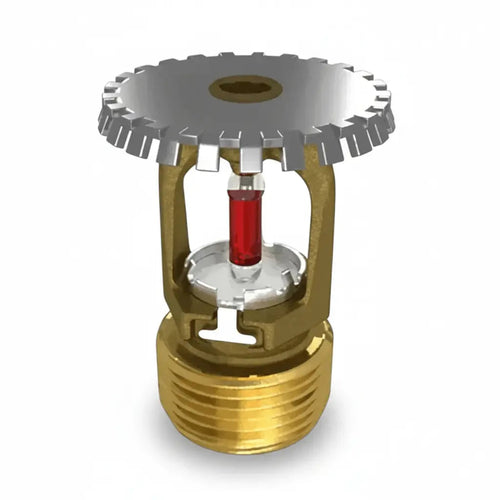


How to Install a Sight Glass on a Sprinkler Riser
A sight glass on a sprinkler riser is a pressure-containing component, not a simple viewing accessory. To understand how to install a sight glass on a riser, first isolate and depressurize the system, then fit an assembly with compatible connections and tighten it to the manufacturer’s specified torque. Finish by testing for leaks using the system’s approved procedure.
A clear view into the riser can help with observation, but a poor seal or incorrect installation can compromise system integrity. Each step matters, from choosing a compatible mounting arrangement to checking the gasket and connections before returning the system to service.
This guide covers preparation, fit and material checks, tightening, leak testing, and installation records. It also explains when work calls for qualified fire-protection expertise and how to choose compatible components. The goal is a dependable installation that supports safe, reliable sprinkler-system operation.
Key Takeaways
- Tighten clamp bolts in a cross sequence, increasing torque in stages to help seat the assembly evenly.
- Match gasket material to both the process media and operating temperature to support a reliable seal.
- Inspect the plate and seat before assembly; reject glass with chips on a sealing edge.
- Record the flange and connection details, then use the manufacturer’s specified torque and the applicable test procedure.
- Measure replacement gauge glass carefully, including the distance between valve faces and each valve face’s stop casting.
Even hand-tightening and cross-pattern torqueing
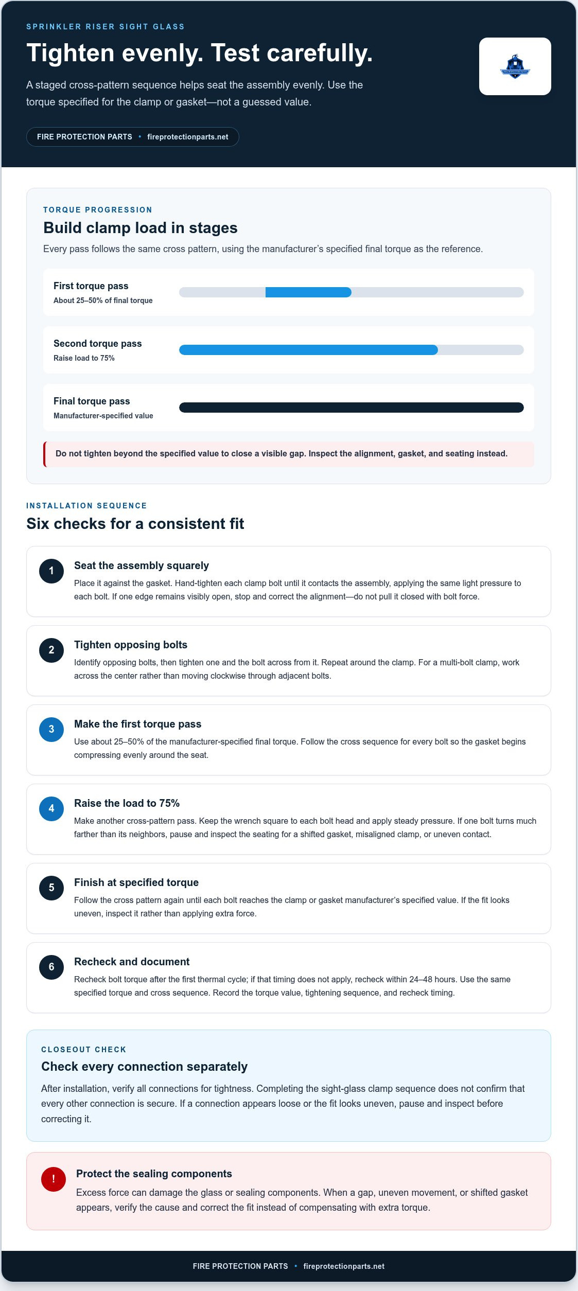
- Set the sight-glass assembly squarely against its gasket before tightening. Hand-tighten each clamp bolt until it contacts the assembly, applying the same light pressure to each bolt. This first pass brings the parts together without pulling one side down ahead of the other. If one edge remains visibly open, stop and correct the alignment instead of using bolt force to close the gap.
- Identify opposing bolts before using a wrench. Tighten one bolt, then the bolt across the assembly, repeating this cross pattern around the clamp. This distributes force more evenly than tightening adjacent bolts in a circle. For a multi-bolt clamp, work across the center rather than moving clockwise from one bolt to the next.
- Make the first torque pass to about 25-50% of the final torque value. Use the torque value specified by the clamp or gasket manufacturer; don’t substitute a guessed value or a general rule. Follow the same cross sequence for every bolt, so the gasket begins compressing evenly around the sight-glass seat.
- Raise the load to 75% of final torque with another cross-pattern pass. Keep the wrench square to each bolt head and apply steady pressure. If a bolt turns much farther than its neighbors, pause and inspect the seating. Uneven movement can indicate a shifted gasket, misaligned clamp, or uneven contact that needs correction before the final pass.
- Make the final pass at the manufacturer-specified torque, following the cross pattern again. Continue around the clamp until each bolt reaches the specified value. Don’t tighten beyond that value to compensate for a visible gap. Inspect the fit and gasket instead, since extra force can damage the glass or sealing components.
- After the first thermal cycle, recheck bolt torque; if that timing doesn’t apply, recheck within 24-48 hours. Some gaskets settle after assembly, which can change clamp loading. Use the same specified torque and cross sequence for the recheck. Record the torque value, tightening sequence, and recheck timing with the installation notes to support consistent maintenance.
The guide says all connections should be checked for tightness after installation. Treat that check as a distinct closeout step, rather than assuming that completing the sight-glass clamp sequence confirms every connection is secure. Review the assembly methodically, keeping the check consistent with the specified torque and cross-pattern approach where those apply. If any connection appears loose or the fit looks uneven, pause to inspect it and correct the condition instead of applying extra force without verifying the cause. Keep the result with the installation notes, alongside the torque value, tightening sequence, and recheck timing already recorded. Clear notes help the next person understand what was checked and what method was followed. A careful final review supports a consistent handoff and helps ensure that the assembly is left in the intended condition before it is put into service.
Gasket fit and material compatibility
- Match the sight glass to the riser opening, connection, and operating conditions. For an existing flange, provide its size so the bolt holes align. Select a pressure rating that suits the system, not just the visible opening. Bolt-on sight glasses are generally specified for either up to 15 lbs. psi or over 15 lbs. psi.
- Choose glass and gasket materials for the actual operating temperature and process media. Soda glass is typically used below 300 °F; borosilicate glass is typically used between 300 °F and 500 °F. Quartz or sapphire glass is recommended above 500 °F. Those temperature ranges guide material selection, but pressure suitability still matters.
- Gather the sight-glass assembly, compatible gasket, hand tools, and a torque wrench. Have the clamp or gasket manufacturer’s torque instructions ready before assembly. Use the specified value, which depends on the components selected. Don’t substitute an assumed torque or a general value from another sight-glass assembly.
- Inspect the gasket before fitting it. Confirm that it matches the seat’s shape and dimensions, lies flat, and has no tears, folds, or hardened areas. Check that its material suits the process media and operating temperature. A gasket can match the outline yet still lose sealing performance or deteriorate if its material is incompatible.
- Clean the mating surfaces without scratching the seat or leaving debris. Place the gasket in its intended position, then set the glass and clamp in place without dragging them across the sealing face. Check that the gasket is centered all the way around. A pinched edge or trapped particle can create a leak path.
- Check compatibility across the whole assembly, not just the gasket. The glass, clamp, fasteners, and connection must suit the riser’s pressure and temperature conditions. For a flange-mounted unit, compare the bolt pattern and seating area with the existing flange. Correct any mismatch before tightening. Bolt force cannot fix an incompatible size or material.
- Once assembled, look around the entire seat for even gasket compression, visible gaps, or excessive extrusion. If the gasket has shifted, release the assembly and reposition it rather than forcing it into place. Use the manufacturer’s specified torque during tightening. For related fire-protection system components, keep material and connection compatibility central to selection.
Pre-installation plate, seat, and gasket checks
- Use a licensed plumber or fire-protection contractor if the work alters sprinkler piping, requires opening a pressurized riser, or involves isolation you can’t safely control. Treat installation on pressurized equipment as pressure-containment work. Follow lockout/tagout and applicable confined-space rules before removing any plate, clamp, or connection.
- Isolate the riser using its designated controls, then drain it and relieve trapped pressure before loosening the assembly. Confirm the section is depressurized, and control discharge so water cannot create a hazard or damage nearby equipment. Never assume a closed valve alone proves the work area is safe.
- Compare the sight-glass plate with the seat before assembly. For DIN7081 plates, check that length, width, and thickness match the DIN7081 code or the measured seat. Reject a plate with a chip on any sealing edge; even a small edge defect can compromise the seal and lead to failure.
- Where conditions permit, inspect the seat and plate for fouling, cracks, and signs of leakage. Remove dirt or residue that could prevent full contact, using a method that won’t scratch the sealing surface. Check the gasket for tears, folds, hardening, or contamination, then confirm it lies flat and centered.
- After positioning the gasket and plate, inspect compression around the entire seat. Look for uniform contact, gaps, or excessive gasket extrusion. Uneven compression can indicate a shifted gasket, damaged seat, or mismatched parts. Correct the cause before returning the riser to service. Extra tightening can damage components without fixing a poor fit.
- Replace soda lime glass discs after maintenance that requires disassembly; do not reuse them. Before reassembly, check that the replacement disc and gasket match the seat, then follow the component manufacturer’s assembly and torque instructions. Clear loose fragments, tools, and debris from the work area so they cannot interfere with the sealing surfaces.
- Test the completed assembly for leaks using the appropriate procedure. A soap-solution test is suggested for low-risk sight-glass systems. Test pressurized systems pneumatically or hydrostatically according to plant procedure. Watch the joint during testing, checking the plate, gasket edge, and connections. Correct any leak before returning the equipment to service.
Make these checks part of the final fit review rather than relying on the component’s overall appearance. A plate may look sound while a small defect at the sealing edge makes it unsuitable. Reject any plate with a chip on that edge. Focus on the sealing surface, and don’t overlook damage just because the fit appears acceptable. This helps prevent a compromised plate from proceeding to reassembly and possible failure.
Review gasket compression as a continuous condition around the seat, not as a check at only one visible point. Compare the contact around the full perimeter, noting whether it remains even and whether any gap or excessive extrusion is visible. If the pattern is inconsistent, pause and reassess the fit before proceeding. A visual check should establish that compression is uniform around the entire seat, with no gaps or excessive extrusion; those conditions are reasons to resolve the fit concern rather than accept it as satisfactory.
Installation documentation
Document the applicable requirements and installation details before restoring the riser to service. Clear records connect the selected sight glass, assembly method, and test results.
-
Review Applicable Codes and Standards
Identify the requirements for the specific plumbing, HVAC, or fire sprinkler riser. The governing code depends on the system and project jurisdiction, so follow the applicable project documents and approval criteria. Sight-glass materials should follow ASME standards. Don’t assume one standard covers every connection, material, and installation condition.
Compare the sight-glass manufacturer’s instructions with the required system documentation. Confirm that the selected plate, gasket, flange, and connection suit the intended service. For an existing flange, provide its size so the bolt holes can be matched. Record the requirements used, including applicable project specifications and approved installation instructions.
Keep material standards separate from installation instructions. ASME guidance for sight-glass materials doesn’t replace the clamp or gasket manufacturer’s torque value. Likewise, a product instruction doesn’t establish every project-specific requirement. Record both references where applicable, and resolve conflicts through the project’s established review process before work begins.
-
Document the Installation
Record the installed assembly and its position on the riser. Note the connection type, flange size, plate and gasket materials, and installation instructions used. Include the specified torque value and tightening sequence. These details help maintenance staff identify what was fitted and how it was secured.
Include the test method and result. A soap-solution test is suggested for low-risk sight-glass systems. Test pressurized systems pneumatically or hydrostatically according to plant procedure. Record the procedure followed, observations at the plate and connections, and any corrective work completed before the system returns to service.
Attach relevant product information and installation notes to the system’s maintenance record. Include the sight-glass identification, gasket compatibility details, and flange measurement used to match bolt holes. Note the date of the first thermal-cycle or follow-up torque check when applicable. This supports consistent future inspections and helps staff identify the correct assembly details.
Keep component information and test results together. A technician investigating a leak should be able to find the assembly details, torque instruction, and test outcome in one record. Update the entry if the glass, gasket, or connection is replaced, so future work reflects the components actually installed.
Measuring replacement glass tubing
- Identify the assembly before measuring. Boiler gauge glass tubing sits between upper and lower valves, while a sprinkler-riser sight glass may use a different assembly. Don’t assume boiler tubing dimensions apply to a riser viewing port. Identify the valve arrangement and replacement part so the measurement matches the equipment being serviced.
- Isolate and drain the boiler gauge glass before removing its tubing. Close the upper and lower gauge-glass valves, drain the glass, then confirm both valves are seated by checking that the glass remains empty. Wear work gloves and proper eye protection as minimum personal protective equipment before handling the glass.
- Measure the replacement glass using the distance between the valve faces plus the distance from a valve face to its stop casting. Use the actual valve faces and stop casting as reference points. Don’t rely only on the removed tube’s overall length: damage or a prior replacement may mean it doesn’t match the installed valve geometry.
- Roll the tube over 180 ° and take a second measurement. Compare the two readings before selecting the replacement. This second check helps reveal whether the tube or measuring position has affected the first result. If the readings differ, repeat the measurement with the tube positioned consistently and use the valve reference points again.
- Record the measurement method alongside the dimensions. Note that the calculation uses the distance between valve faces plus the distance from a valve face to its stop casting. Recording these reference points distinguishes the required installed length from a measurement taken only across the removed tube.
- Compare the replacement tube with the valve arrangement before installation. Confirm that its measured length matches the reference points and that it seats correctly at both ends. Don’t force a tube that appears too long, too short, or misaligned. A mismatch can prevent proper seating and compromise the gauge assembly.
- After installation, slowly open the gauge glass valves. This allows temperature and pressure to rise steadily. Monitor the tubing and connections for leaks as the glass returns to service. For sprinkler-riser projects, keep boiler gauge tubing separate from the sight-glass assembly, and review fire-protection system components suited to the system.
Fire Protection Parts: Viking Plastics CPVC Pipe for Fire Protection
Fire Protection Parts offers Viking Plastics CPVC Pipe for Fire Protection for projects involving fire-protection piping components. A sight glass and riser piping serve different purposes, so selecting pipe doesn’t replace the need to match the viewing assembly, gasket, and connection to system requirements.
Consider this offering when sourcing CPVC pipe for a fire-protection project, alongside other system components such as Residential Fire Pump Systems, PTR Electric Deluge VXD, or ASC Seismic Bracing. Match product selection to the system design and component needed. For fire-protection components, contact Fire Protection Parts.
Keep the Next System Decision Aligned
Knowing how to install a sight glass on a riser is one part of matching fire-protection equipment to its purpose. Next, consider how each component fits the system design, operating conditions, and maintenance plan. Clear records of selections and changes help teams make consistent decisions as equipment needs evolve.
For related system components, Fire Protection Parts offers Viking Plastics CPVC Pipe for Fire Protection, Residential Fire Pump Systems, and PTR Electric Deluge VXD. These products serve different fire-protection applications, so choose the one your project requires, not as a substitute for a sight-glass assembly.
Explore the available offerings or visit Fire Protection Parts to take the next step in sourcing fire-protection components. Careful selection keeps your project focused and supports confident decisions.
Frequently Asked Questions
What type of riser is a sight glass installed on, and what is it used for?
A sight glass belongs on a sprinkler riser designed to accept a compatible viewing assembly. It provides a visual view through that assembly, not a substitute for system controls or a separate flow-measuring device. Knowing how to install a sight glass on a riser starts with identifying the riser design and intended purpose. Boiler gauge-glass tubing is a different assembly and shouldn’t be assumed suitable for sprinkler piping.
What are the steps for installing a flanged sight glass on a riser?
Match the sight-glass flange to the riser flange, including its bolt-hole pattern and sealing-face dimensions. Isolate and depressurize the piping, inspect both faces, position the compatible gasket, and align the bolt holes without forcing the assembly. For anyone learning how to install a sight glass on a riser, the flanged connection must fit the existing piping correctly. Hand-start the fasteners, tighten to the manufacturer’s specified torque, then test according to plant procedure.
How do you install a threaded sight glass on a riser?
Confirm that the sight glass and riser have matching thread types and sizes before assembly. Isolate and depressurize the piping, then inspect the threads for damage or debris. Apply thread sealant only if the fitting instructions require it and specify a compatible type. Start the connection by hand to prevent cross-threading, then tighten using the fitting’s wrench flats, not the glass body. Test the joint according to the applicable procedure.
What gasket, sealant, and bolt torque should be used for a riser sight glass?
Choose a gasket compatible with the system media and operating temperature, and use the torque value specified by the clamp or gasket manufacturer. There is no universal bolt-torque value for every assembly. For threaded connections, apply sealant only when the fitting instructions require it and specify a compatible type. Keep sealant off flange gasket faces unless the assembly instructions explicitly direct otherwise.

