



How to Install a Tamper Switch and Connect Its Panel Signals
A valve that looks open can still be moved, so its position needs a reliable signal. Learning how to install a tamper switch starts with fitting the supervisory device to the fire-protection valve and connecting it so a change from the open position is reported to the fire control panel. Because a valve’s position may not be continuously observed, a tamper switch can provide a supervisory signal if it moves from the open position.
A tamper switch supervises a fire protection system; it does not usually sound the fire alarm directly. In most jurisdictions, its signal goes to the fire control panel, while the Authority Having Jurisdiction determines local requirements. This guide explains what tamper switches do, how professionals install post indicator valve switches, and how the signals reach the panel, so you can understand the process without compromising fire protection reliability.
Key Takeaways
- Understand how a tamper switch detects valve movement and reports a supervisory signal to the fire control panel.
- Learn the key considerations for fitting a switch to a fire sprinkler control valve, including a post indicator valve.
- See what tools and materials the installation may require, and why the valve and switch design matter.
- Follow the testing and reset process to confirm the signal reaches the panel and the valve returns to its normal position.
What is a Tamper Switch for Fire Protection Systems?
A fire protection tamper switch monitors whether a control valve remains in its required position. Its actuator, typically a lever or cable, detects movement when the valve partially or fully closes. The switch then sends a supervisory signal to the fire control panel. In most jurisdictions, this signal does not directly trigger the fire alarm; the Authority Having Jurisdiction (AHJ) determines local requirements.
A post indicator valve (PIV) is outside the building, with its gate underground at the bottom of its stem or post. Because the valve’s position may not always be visible, a tamper switch can indicate if it moves. An OS&Y valve offers a visible reference: its screw or stem sticks up when open. Some butterfly valves come with preinstalled tamper switches, so the valve and switch arrangement matters before work begins.
The NFPA provisions and local fire regulations that apply to an installation depend on the requirements adopted for that project. The AHJ determines local requirements, including how the supervisory signal must reach the fire control panel.
A qualified professional should install or work on a tamper switch, including when removing, replacing, or adjusting it. Licensing and permit requirements vary by jurisdiction, so follow the AHJ’s local rules.
Installation costs depend on the switch type, valve configuration, wiring distance, panel compatibility, and professional labor. These factors determine the scope of work; a post indicator valve setup may differ from a valve with a preinstalled switch.
Common mistakes include misaligning the actuator, leaving wiring disconnected, or interfering with the switch during valve work. A misaligned lever may not detect movement, and a broken connection may prevent the panel from receiving the signal. Knowing how to install a tamper switch means preserving the valve’s required position and maintaining a reliable signal path. Never bypass the switch to silence a supervisory condition; find and correct the cause instead.
How do you install a tamper switch on a fire sprinkler control valve?
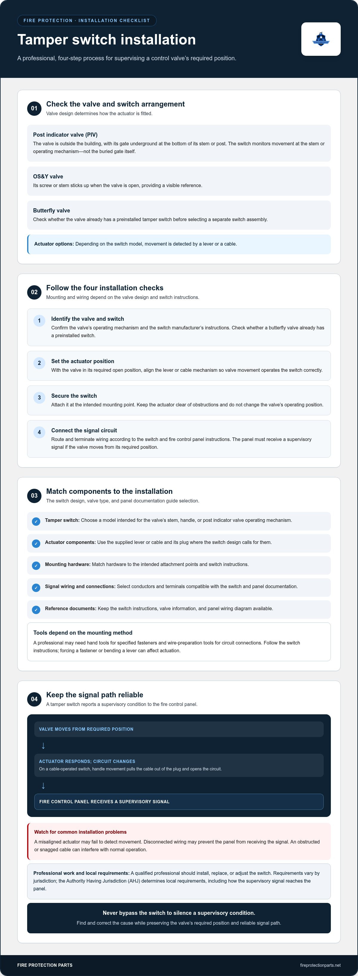
A qualified fire protection professional should install, replace, or adjust a tamper switch. Mounting and wiring depend on the valve design and switch type. Post indicator valves (PIVs), OS&Y valves, and butterfly valves each have different actuator arrangements.
On a cable-operated switch, the cable wraps around the valve stem or handle. With the valve in its required position, the professional secures the cable end in the switch plug. If someone turns the handle, the cable moves out of the plug, opening the circuit and signaling the control panel. Position the cable so it responds to valve movement without obstructing normal operation.
A typical installation follows a deliberate sequence:
- Identify the valve and switch. Confirm the valve’s operating mechanism and the switch manufacturer’s instructions. Check whether a butterfly valve already has a preinstalled switch.
- Set the actuator position. With the valve in its required open position, align the lever or cable mechanism so movement operates the switch correctly.
- Secure the switch. Attach the device to its intended mounting point. Keep its actuator clear of obstructions and avoid changing the valve’s operating position.
- Connect the signal circuit. Route and terminate the switch wiring according to the device and fire control panel instructions. The panel must receive a supervisory signal when the valve moves from its required position.
A PIV’s outdoor location and underground gate mechanism affect the installation. The switch monitors movement at the valve stem or operating mechanism, not the buried gate itself. One supervisory switch model may use a cable, while another uses a lever actuator.
These are process steps, not a do-it-yourself wiring guide. A qualified professional must preserve the valve’s function and the signal path. For related sprinkler-system planning, explore air compressors for sprinkler systems.
With a cable-operated switch, a change in the circuit lets the control panel register handle movement and indicate that the valve has left its required position.
What tools and materials are needed to install a tamper switch?
The switch design and valve type determine which materials are needed. A cable-operated supervisory switch requires its switch assembly and cable; a lever-operated model needs clear space for its operating arm. A butterfly valve with a preinstalled switch may not need a separate switch assembly. The professional checks the valve arrangement and manufacturer’s instructions first.
Select materials to match the device and fire control panel:
- Tamper switch: Choose the model intended for the valve’s operating mechanism, such as a stem, handle, or post indicator valve.
- Actuator components: Use the supplied lever or cable and its plug where the switch design calls for them.
- Mounting hardware: Use hardware suited to the designated attachment points and the switch instructions.
- Signal wiring and connections: Select conductors and terminals compatible with the switch and panel documentation.
- Reference documents: Keep the switch instructions, valve information, and panel wiring diagram available for the installation.
Tools depend on the mounting method. A professional may need hand tools for the specified fasteners and wire-preparation tools for circuit connections. Follow the switch instructions to select suitable tools; forcing a fastener or bending a lever can affect actuation. A cable-operated model also needs enough space to route and secure the cable without snagging the valve handle.
Before starting, compare the switch terminals with the fire control panel diagram to identify the intended supervisory circuit and connection points. Keep wiring clear of moving parts, including an OS&Y stem that rises as the valve opens. The switch must detect movement without restricting valve operation.
No single tool kit suits every valve. A PIV, an OS&Y valve, and a butterfly valve with a preinstalled switch may require different mounting arrangements. A qualified professional should handle installation, replacement, and adjustment, matching materials and tools to the specific switch, valve, and panel documentation.
How do you test and reset a newly installed tamper switch
A qualified fire protection professional should test the switch after installation. Testing confirms that valve movement changes the switch state and that the fire control panel receives the expected supervisory signal. Follow the switch manufacturer’s instructions and the panel configuration guide.
Before testing, the professional identifies the valve’s normal position and the panel point associated with its switch. This establishes a clear baseline. Keep the valve under controlled supervision during testing, because changing its position can affect fire protection.
A functional check typically follows this sequence:
- Confirm normal status. Check the valve’s required position and verify the panel displays its normal state.
- Operate the test movement. The qualified professional moves the valve or actuator as directed by the switch instructions. Don’t force a lever or cable beyond its operating range.
- Observe the switch. Confirm that the actuator responds to the movement and changes the circuit state.
- Verify panel receipt. Check that the correct panel point shows a supervisory signal. A switch movement without a corresponding panel indication points to a connection, alignment, or configuration issue.
- Restore the valve. Return it to its required operating position, then confirm the switch and panel return to their normal states.
Reset behavior depends on the switch and panel arrangement. The professional follows the manufacturer’s procedure and the panel’s operating instructions, then verifies the normal indication. Acknowledging a signal at the panel alone does not correct a valve left out of position or a switch that has not returned to normal.
Document the test result, valve position, and any corrective adjustment in the system’s records. If the supervisory signal fails to appear or clear, the professional investigates before treating the test as complete. For related fire protection system components, explore fire protection equipment.
Fire Protection Parts: Viking Plastics CPVC Pipe for Fire Protection
Fire Protection Parts offers specialized CPVC Pipe for Fire Protection for projects that use CPVC sprinkler piping. Once the tamper-switch requirements and panel signal path are clear, choosing suitable system components is a practical next step. This pipe is relevant when the project calls for CPVC fire protection piping; select it to match the system design and project requirements.
For other fire protection system needs, Fire Protection Parts also offers Residential Fire Pump Systems, PTR Electric Deluge VXD, and ASC Seismic Bracing. These components serve different applications and are not substitutes for a correctly installed and tested tamper switch. Match each product to the part of the system it is designed to support.
Explore available CPVC pipe for fire protection and related components at Fire Protection Parts, or contact the company with questions about its products.
Make the Next System Decision With Confidence
A reliable fire protection system depends on compatible components and sound decisions at every stage, from planning through professional installation. Knowing how to install a tamper switch is one part of the process; each component must also match the system design and intended operation. Identify the equipment your project needs and how each item fits into the complete system.
Fire Protection Parts can help you explore fire protection components for your project, including options for piping, residential pumping, and deluge systems. For product questions or help identifying the next step, contact Fire Protection Parts. A thoughtful equipment decision supports a more organized project and helps you move forward with clarity.
Frequently Asked Questions
What is a tamper switch and what does it monitor?
A tamper switch monitors the position of a fire protection control valve, not smoke or heat. It detects movement that may partially or fully close the valve and compromise the sprinkler water supply. For example, it can supervise a valve controlling that supply, while a separate fire alarm detector responds to fire conditions. Its signal alerts the system to a valve-position change that needs follow-up.
How do you wire a tamper switch to a fire alarm control panel?
A qualified professional connects the switch circuit to the designated supervisory input, following the switch and panel manufacturers’ instructions. Terminals and wiring arrangements vary by device, so there is no universal terminal map. Keep conductors clear of moving valve parts, and test that the panel identifies the correct supervisory point. Never bypass or alter the circuit to silence a signal.
How much does a tamper switch and professional installation cost?
Costs depend on the switch type, valve configuration, wiring distance, panel compatibility, and professional labor. A post indicator valve setup may differ from a valve with a preinstalled switch.

