



How to Install Grooved Couplings for Fire Protection Pipes
A grooved joint is only as reliable as its seal and alignment. To understand how to install a grooved coupling, prepare the pipe ends, check that the grooves are clean and undamaged, seat the gasket as directed, and tighten the housing evenly. The joint’s final position matters: rigid couplings need an even gap on both sides, while flexible grooved joints should have no gap.
It’s easy to focus on the coupling halves and bolts, but the gasket and pipe-end condition matter just as much. A damaged groove, misplaced gasket, or uneven tightening can compromise the connection. Follow the installation instructions for the specific coupling and pipe materials.
This guide covers how to prepare and align pipe ends, inspect grooves, lubricate and position the gasket, and assemble the coupling components. It also compares grooved joints with flanged and welded connections, explaining how the methods differ and where each may suit a fire protection piping project.
Key Takeaways
- Prepare pipe ends and inspect grooves before assembly to help the coupling seat correctly.
- Align the pipe ends to suit the joint type: rigid joints need an even gap on both sides, while grooved joints should have no gap.
- Protect the seal by positioning the gasket correctly and using the lubricant specified for the coupling.
- Compare grooved, flanged, and welded joints by installation method and project needs before selecting a connection.
Comparison with flanged and welded joints
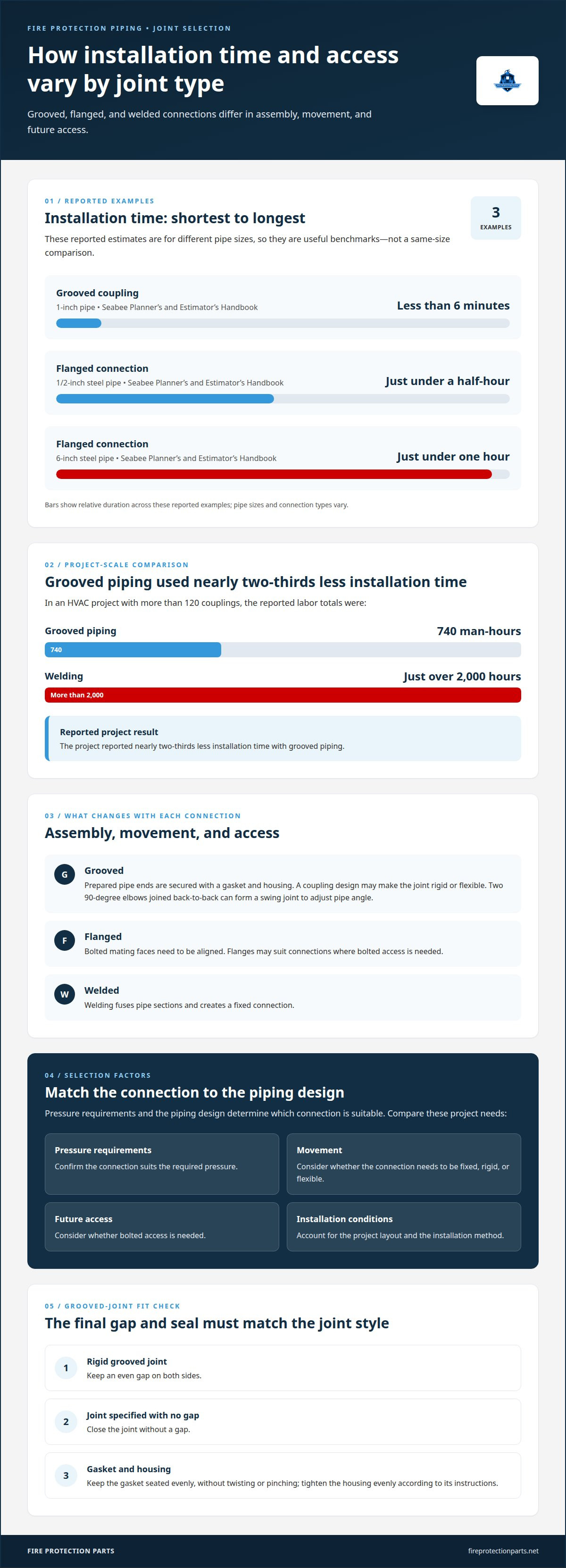
Grooved couplings connect prepared pipe ends with a gasket and housing. Flanges use bolted faces, while welding fuses pipe sections. The connection type affects assembly, alignment, and future access. A grooved joint can be rigid or flexible, depending on the coupling design. Flanged joints depend on aligned mating faces, and welded joints create a fixed connection. Pressure requirements and the piping design determine which connection is suitable.
Installation time differs by joint type and pipe size. The Seabee Planner’s and Estimator’s Handbook estimates less than six minutes to install a grooved coupling on 1-inch pipe. Its estimate for a flange on 1/2-inch steel pipe is just under a half-hour; on 6-inch steel pipe, just under one hour. In an HVAC project with more than 120 couplings, grooved piping took 740 man-hours, compared with just over 2,000 hours for welding. The project reported nearly two-thirds less installation time with grooved piping.
After assembly, check the joint gap and gasket position around the pipe. A rigid grooved joint needs an equal gap on both sides; a grooved joint specified to have no gap should close without one. The seal should sit evenly, without twisting or pinching. Common mistakes include misaligned pipe ends, damaged grooves, a displaced gasket, and uneven bolt tightening. Avoid them by inspecting the pipe ends, centering the gasket, and tightening the housing evenly according to its instructions.
Grooved fittings also allow practical changes in direction. Two 90-degree elbows joined back-to-back create a swing joint, which can adjust the pipe angle. That flexibility can help accommodate layout changes without cutting and rewelding the pipe. Flanges may suit connections that need bolted access, while welded joints provide a fixed connection. Compare the required pressure, movement, access, and installation conditions before selecting the joint.
Aligning pipes and coupling grooves
Support both pipe sections first so their ends stay steady during alignment. Bring the ends together without forcing them sideways, then align their centerlines. A tilted connection can load the gasket unevenly or prevent the coupling housing from seating properly. Check the outlet direction against the piping layout before tightening anything. Make small alignment adjustments before assembling the housing.
Grooved and shouldered pipe joints are covered by ANSI/AWWA C-606. Use the manufacturer’s instructions for the specific coupling to guide assembly, including the required pipe-end position and joint style. The standard and the product instructions serve different purposes: one covers grooved and shouldered joints, while the maker’s instructions address that coupling’s installation.
Confirm the intended joint gap before closing the coupling. For a rigid grooved joint, the gap must be equal on both sides; a grooved joint specified to have no gap should have no gap. Check the full circumference rather than judging from one angle. If one side appears wider, realign the pipe ends before tightening. The coupling should sit squarely over both grooves, not across a crooked connection.
For safety, keep the pipe supported and follow the coupling maker’s assembly instructions. Don’t work where pipe movement or stored pressure could cause a sudden release, and wear appropriate protective equipment when handling pipe and tools.
- Support the pipe sections and orient each outlet to match the planned connection.
- Bring the ends into alignment without forcing or twisting them.
- Check the required gap on both sides, using the specified rigid or no-gap joint arrangement.
- Position the coupling over both grooves, then tighten it as directed by its manufacturer.
Recheck alignment after tightening. A shifted pipe can pull the joint out of position, while uneven gaps can signal that the connection needs adjustment. Correct the alignment before continuing to the next connection.
Checking groove dimensions and cleaning pipe ends
Before assembly, compare each groove with the coupling manufacturer’s dimensional requirements. Check groove diameter, width, and position using the specified measuring tools. Don’t rely on appearance alone: a groove can look even while its dimensions prevent the housing keys from engaging correctly. Inspect the full circumference for an interrupted cut, flattened area, crack, or other damage. If the groove is irregular, stop and correct the pipe before fitting the coupling.
Grooving method depends on pipe construction and the coupling instructions. Cut grooving is typically used on Schedule 30 and heavier pipe. Whatever method is used, remove burrs and sharp edges without changing the groove profile. For example, a tool mark that leaves a raised ridge near the groove can interfere with seating. Keep the measuring tool square to the pipe so readings reflect the groove itself, not a tilted measurement.
- Measure the groove against the manufacturer’s requirements for that pipe and coupling.
- Inspect the groove around the entire pipe for damage, uneven edges, or debris.
- Check the pipe end for dents, burrs, and sharp edges that could affect the gasket.
- Clean the gasket-contact area before assembly.
Clean the pipe end and the surface where the gasket will seal. Remove dirt, loose scale, chips, and other residue using a method suitable for the pipe material. Debris trapped beneath the gasket can create a leak path, while a sharp edge can cut or catch the rubber during installation. Keep the cleaned surface free of debris as you position the coupling.
Finish with a visual check and, if the groove was repaired or recut, recheck its dimensions. Confirm that the pipe end is smooth where the gasket rests and that the groove remains consistent around the pipe. These checks prepare the grooved pipe for assembly without forcing mismatched components to fit.
Grooved coupling components and sealing
A grooved coupling uses a gasket, housing segments, and fasteners to secure the pipe joint. Rigid couplings limit movement between pipe ends; flexible couplings allow movement within the coupling’s design. Use the joint type specified for the piping layout, rather than treating the two styles as interchangeable. The coupling body described here conforms to ASTM A536 Grade 65-42-12.
Gather the matching coupling housing, gasket, bolts, nuts, silicone lubricant, and tools required by the manufacturer. Use a torque wrench if the instructions specify a torque value. Match every component to the coupling and pipe; incompatible parts can prevent the housing from seating or the gasket from sealing properly.
Apply silicone lubricant to the pipe end, the gasket’s outer surface, and its sealing lip, following the coupling instructions. Don’t use petroleum-based lubricant. Fit the gasket over the pipe end, then bring the pipe ends together as directed. Position the housing segments so their keys engage both grooves. Keep the gasket centered and check that it hasn’t rolled, twisted, or slipped out of place.
Tighten the nuts alternately and evenly so pressure distributes across the gasket. For VGS couplings with stainless steel track bolts, the listed torque range is 25-45 lb-ft for a 1/2-inch bolt, 65-150 lb-ft for a 3/4-inch bolt, and 105-175 lb-ft for a 7/8-inch bolt. After the bolt pads contact metal to metal, VGS instructions call for an additional one quarter to one half turn. Follow the instructions for the specific coupling, since torque depends on the specified assembly. Excessive torque can damage the housing or bolts and compromise the connection.
- Seat the gasket evenly before fitting the housing.
- Use silicone lubricant, not petroleum-based lubricant.
- Tighten both sides evenly with the specified tool and torque.
Fire Protection Parts
Fire Protection Parts helps you source fire protection system components for the wider piping project. Once the coupling type and installation requirements are clear, consider how the connected pipework fits the system. Specialized CPVC Pipe for Fire Protection serves projects specifying CPVC piping, while Air Compressors for Sprinkler Systems are for sprinkler systems that require air. Other available categories include Residential Fire Pump Systems, PTR Electric Deluge VXD, ASC Seismic Bracing, and Anti-freeze for Fire Protection.
These components address different system needs, so select them according to the project design, rather than viewing them as substitutes when learning how to install a grooved coupling. For product information related to your fire protection piping project, contact Fire Protection Parts.
Carry the connection into the wider project
A sound joint depends on more than the coupling itself. The surrounding fire protection design, pipe material, and system components must work together. Before moving from one connection to the full piping plan, consider how the selected joint fits the project requirements and how nearby components affect access and layout. This broader view helps keep installation decisions consistent across the pipework.
Knowing how to install a grooved coupling provides a clear basis for planning the connection, but each project depends on compatible components and manufacturer instructions. Fire Protection Parts can help you source fire protection products relevant to your system plan.
Contact Fire Protection Parts to discuss the products that fit your fire protection project. Take the next step with a clear plan and keep the system’s requirements at the center of every decision.
Frequently Asked Questions
How to Install Grooved Couplings?
To understand how to install a grooved coupling, treat the pipe, gasket, and housing as a matched assembly. Before starting, confirm that the coupling suits the pipe material, dimensions, and intended system conditions. Then follow the product instructions from preparation through final tightening. Don’t substitute a gasket or fastener from another coupling model, even if it appears to fit.
How do you prepare and groove pipe ends for a grooved coupling?
Prepare each pipe end using the grooving method and dimensions specified for the selected coupling. Cut grooving is typically used on Schedule 30 and heavier pipe. Remove burrs and debris, then inspect the groove around its full circumference for irregularities or damage. A clean, consistent groove helps the coupling keys engage as intended; a damaged profile needs correction before assembly.
What are the steps for assembling a grooved coupling?
First, confirm that the coupling body, gasket, bolts, and nuts match the pipe and joint design. Lubricate and position the gasket as the manufacturer directs, then place the housing so its keys engage the grooves. Install the fasteners and tighten them evenly using the specified method. Before proceeding, inspect the assembled joint for displaced gasket material or an unevenly seated housing.
How do you align pipe ends and position the gasket correctly?
Support the pipe sections so their weight doesn’t pull the connection out of line. Position the gasket on the sealing area without stretching or twisting it, then bring the pipe ends together as required for that coupling. Check the gasket around the circumference before placing the housing. If it folds or shifts during assembly, reposition it rather than forcing the coupling closed.
How do you inspect and pressure-test a grooved coupling installation?
Inspect the completed assembly for an evenly seated housing, engaged keys, visible gasket displacement, and fasteners tightened as instructed. Pressure testing should follow the project’s approved test procedure and the coupling manufacturer’s directions, including the specified test conditions. Observe the connection during testing for leakage or movement. If a problem appears, make the system safe and address it according to the applicable procedure.

