



Potter and System Sensor Flow Switches for Fire Protection
There is no universal winner in a Potter and System Sensor flow switch comparison. The right model depends on whether it is UL Listed, its FM approval, activation threshold, and sensitivity in your system. These details matter because they determine whether a waterflow switch suits the intended fire alarm application, and models from the same manufacturer can differ. Compare model-specific approvals, activation characteristics, and installation requirements against your system design.
Key Takeaways
- Compare UL Listed status and FM approval for the specific switch model and its intended application, not just by manufacturer name.
- Assess activation threshold and sensitivity against the sprinkler system’s design and expected waterflow conditions.
- Use the model’s documentation to match switch type and pipe compatibility to the system configuration.
- Plan installation and alarm-panel verification together so the switch signal can be tested as part of the connected system.
UL Listed and FM approval
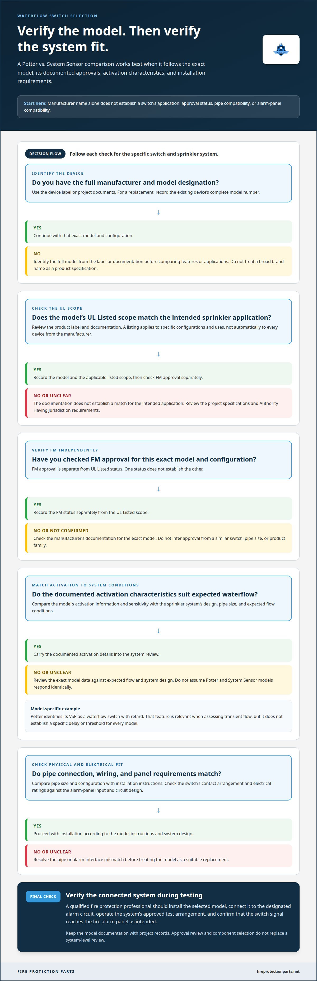
For a Potter or System Sensor waterflow switch, assess UL Listed status and FM approval by exact model, not brand alone. UL Listed means the product is listed by UL for its stated scope. That scope matters: a listing applies to specific product configurations and uses, not every device made by the manufacturer. Read the model’s product label and documentation, then match the listed application to the sprinkler system design.
FM approval is separate from UL Listed status. One does not establish the other, so record each status independently when comparing switches. A model may have one, both, or neither for a particular application. Check the manufacturer’s documentation for the exact model and configuration. Do not infer an approval from a similar-looking switch, a different pipe size, or another product family.
Use a short verification sequence before selection:
- Identify the full model number and configuration.
- Confirm the UL Listed scope matches the intended sprinkler application.
- Check FM approval separately for that model.
- Compare those records with the project specifications and Authority Having Jurisdiction requirements.
How do you install and test a Potter or System Sensor sprinkler waterflow switch? A qualified fire protection professional should install the selected model according to its manufacturer instructions and the system design, then connect it to the designated alarm circuit. During testing, operate the system’s approved test arrangement and confirm that the switch signal reaches the fire alarm panel as intended.
Neither approval replaces a system-level review. A suitably listed switch can still be wrong for the project’s specified application or alarm interface. A useful Potter flow switch vs. System Sensor comparison is model-specific: verify UL Listed scope, FM status, installation instructions, and panel connection requirements together. Keep the model documentation with project records to clarify the selection during installation and commissioning.
Flow activation threshold and sensitivity
A waterflow switch responds when water movement reaches its activation conditions. The threshold depends on the model and system configuration, so compare product documentation instead of assuming Potter and System Sensor devices respond identically. Pipe size, flow conditions, and any retard feature can affect the signal.
Sensitivity matters because a switch must respond to sprinkler waterflow without treating every brief pressure change as an alarm. For example, Potter identifies its VSR as a waterflow switch with retard. That feature is relevant when assessing transient flow, but it does not establish a specific delay or threshold for every model. Use the exact model’s data and system design to determine fit.
There is no basis here for ranking either brand’s reliability, durability, or false alarm rate. Those outcomes depend on the model, installation, system conditions, and maintenance. Compare documented performance consistently, then confirm the installed device operates as intended.
Wiring compatibility depends on the model and alarm panel. Check the switch’s contact arrangement and electrical ratings against the panel input and circuit design, then test that the panel receives the intended waterflow signal. The brand name alone does not establish compatibility.
Warranty coverage and technical support are specific to the manufacturer and model. Compare the written terms for the exact switch instead of assuming Potter and System Sensor offer identical coverage or support.
For selection, review the model’s activation information, retard characteristics, wiring details, and application together. Relate them to the sprinkler system’s expected flow and alarm-panel configuration. Sensitivity is a project-specific decision, not a brand-wide label.
Which Potter and System Sensor flow switch models are commonly used in fire sprinkler systems?
Start with the device’s full name and model number, not just the manufacturer. Potter’s VSR waterflow switch with retard is one identifiable example. For a System Sensor device, use the exact model designation on its label and documentation before comparing features or applications.
These names are not interchangeable product specifications. “VSR” identifies a Potter model family, while “System Sensor” identifies a manufacturer. A fair comparison pairs a specific Potter model with a specific System Sensor model and evaluates each product’s stated use, connection details, and documentation. Do not treat one product family as representative of every switch from its manufacturer.
Use this model-identification sequence for a replacement or new selection:
- Record the manufacturer and complete model number from the existing device or project documents.
- Match that model to its own installation and product documentation.
- Compare the stated application and system connection requirements side by side.
- Carry the exact model designation into submittals and procurement records.
For example, assess a Potter VSR replacement as that specific model, including its retard designation. Identify a System Sensor alternative by its own full model number rather than assuming it is equivalent because it serves a similar purpose. The model documentation, not a broad brand comparison, establishes which details apply.
Common use varies with project specifications, existing equipment, and system configuration. An exact model comparison is more useful than a general popularity claim. To match an installed switch, start with its label and records. For a new system, use the specified application to narrow the options, then check compatibility with the pipe size, installation, and alarm-panel connection. This ties procurement and design decisions to identifiable devices rather than assumptions about either brand.
Potter vs System Sensor Flow Switch Pipe Compatibility
Pipe compatibility depends on the exact Potter or System Sensor model, its connection method, and the sprinkler piping where it will be installed. The manufacturer’s name alone does not establish a match. Start with the pipe size and configuration in the system documents, then compare them with the model’s installation instructions and stated application.
Check the installation location as well as the nominal pipe size. A switch intended for one pipe arrangement may not suit another location or configuration. A replacement, for example, must fit the existing piping and provide the intended waterflow signal without conflicting with nearby fittings or the alarm connection. Confirm these details before selecting a substitute.
Use this comparison sequence for either brand:
- Record the existing pipe size, material, and installation location.
- Identify the full switch model and its specified connection requirements.
- Compare the switch’s application and permitted pipe configuration with the project documents.
- Review any proposed replacement against the existing system and alarm-panel design.
Compare Potter and System Sensor products model by model. A product family name does not prove that every model fits the same pipe sizes or system types. Matching the nominal pipe size alone, for example, may leave connection style or installation location unresolved. Keep the model documentation with the selection record to make the basis for compatibility clear during procurement and installation.
For a new system, use the design documents to define the pipe configuration before choosing a switch. For replacement work, use the installed device and piping as reference points, then confirm the proposed model’s requirements. Source fire protection components with those project details in view to support a more precise match.
Installation and alarm-panel verification
Install the selected Potter or System Sensor model according to its instructions and the sprinkler system design. The switch’s location, mounting orientation, and connection method affect its operation. A qualified fire protection professional should coordinate the work with the system’s alarm interface and project requirements.
Before installation, identify the model and review its wiring diagram. Compare the switch contacts and electrical ratings with the intended panel input. Identify the system circuit and the panel response expected when the switch detects waterflow. These checks help prevent a physically suitable device from being connected incorrectly.
Use an ordered verification process:
- Confirm the model and installation instructions match the selected device.
- Prepare the system and work area according to project procedures.
- Mount and wire the switch using the documented connection points.
- Restore the system condition and perform the approved operational test.
- Observe the panel response and record the test result.
During testing, confirm that the intended waterflow alarm reaches the correct panel indication. If the panel shows a trouble condition instead, compare the field wiring, circuit assignment, and device contacts with the drawings and manufacturer documentation. On an addressable system, confirm the intended device indication. On a conventional circuit, confirm the assigned alarm input responds as designed.
For closeout, record the switch model, circuit or device identification, test outcome, and any corrective work. Keep those records with the project documentation. They provide a clear reference for future service and help maintenance teams distinguish a tested installation from an undocumented device replacement.
Verify Potter and System Sensor switches through the same project-specific process, but do not treat their model instructions or wiring details as interchangeable. Assess each installation as its own configuration. Final acceptance depends on the selected model, system design, panel behavior, and applicable project requirements working together.
Make the Next Selection With Confidence
Let the project requirements guide the next procurement step. A switch decision affects more than the device itself: the component must suit the intended system and its documented design. Keep model information and system requirements together when coordinating related equipment.
Fire Protection Parts helps contractors and facility buyers source fire protection components and find products for their projects. Related offerings include Viking Plastics CPVC Pipe for Fire Protection, Residential Fire Pump Systems, and PTR Electric Deluge VXD. These are separate product categories, so select them only when they fit your project scope.
When choosing between a Potter flow switch and System Sensor, prioritize a model that aligns with the system design and can be documented through installation and testing. This gives your team a clear basis for procurement and project coordination.
Contact Fire Protection Parts for help with sourcing components for your fire protection project. A careful selection now supports a more orderly path from planning to system commissioning.
Frequently Asked Questions
What certifications and fire-code requirements apply to Potter and System Sensor waterflow switches in the United States?
Requirements depend on the exact switch model, project specifications, and the Authority Having Jurisdiction. Check whether the device is UL Listed for its intended application and whether FM approval is required by the project. NFPA 13 installation requirements may also apply to the sprinkler system. A certification by itself doesn’t establish that a specific model meets every project or local requirement.
What are the activation delay and sensitivity specifications for comparable Potter and System Sensor flow switches?
Activation thresholds depend on the exact model and system configuration, including pipe size, flow conditions, and any retard feature. Potter identifies its VSR as a waterflow switch with retard, but no specific delay or sensitivity values are provided.

