



Seismic Sway Bracing for Building Piping and Equipment
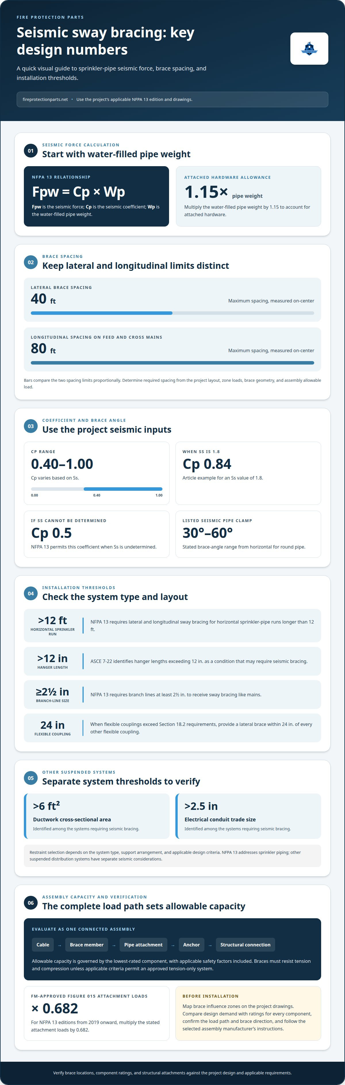
Seismic sway bracing restrains suspended piping against lateral and longitudinal movement, and a sound installation starts by calculating the seismic force on water-filled sprinkler pipe. NFPA 13 uses Fpw = CpWp, with the water-filled pipe weight multiplied by 1.15 to account for attached hardware.
To understand how to install seismic sway bracing, you need to assess the project’s seismic requirements, brace layout, and the allowable load of each assembly. NFPA 13 limits lateral brace spacing to 40 ft. on-center and longitudinal brace spacing on feed and cross mains to 80 ft. on-center.
This guide explains how forces act on suspended systems, how sprinkler-pipe seismic loads are calculated, and what to verify when selecting and positioning bracing components.
Key Takeaways
- Assess the complete brace assembly, since its allowable load is limited by its weakest component and the applicable safety factors.
- Account for how brace direction, attachment geometry, and tension or compression affect restraint performance.
- Plan restraint for each suspended system based on its movement, layout, and applicable design requirements.
- Determine project bracing needs from seismic risk, building use, and structural system specifications.
Allowable loads for cable braces, anchors, and sprinkler pipe
Select braces based on the force assigned to their zone and the allowable capacity of the complete load path. Compare the design demand with the ratings of the cable, attachments, anchor, and supporting structure.
Brace Influence Zones
A zone of influence identifies the piping area whose seismic demand transfers to a particular brace. Use the project drawings to identify the pipe segments, fittings, and attached hardware assigned to each lateral or longitudinal brace. NFPA 13 requires seismic calculations and zone-of-influence information on sprinkler drawings under Section 27.1.3. This mapping helps prevent pipe weight or hardware from being omitted from the brace demand.
Capacity of Brace Components
The complete assembly’s allowable capacity is governed by its lowest-rated component, with applicable safety factors included. Evaluate the cable, brace member, pipe attachment, anchor, and structural connection as a single load path. Braces must resist both tension and compression unless the applicable criteria permit an approved tension-only system. Any tension-only assembly must be approved for its intended use and installed according to its guidelines. Never treat one hardware rating as the capacity of the complete assembly.
Load and Spacing Assessments
Determine required spacing from the project layout, zone loads, brace geometry, and each component’s allowable load. To calculate spacing, angle, and capacity, assign the supported area to each brace, assess its demand, then compare that demand with the assembly’s weakest rating. For round pipe, a listed seismic pipe clamp’s stated brace-angle range is 30°-60° from horizontal. Cp varies from 0.40 to 1.00 based on Ss; for Ss of 1.8, Cp is 0.84. If Ss cannot be determined, NFPA 13 permits Cp of 0.5.
Common mistakes include overlooking an attachment’s lower rating, misaligning hardware, or selecting a brace that resists tension but not compression. For NFPA 13 editions from 2019 onward, multiply the stated FM-approved Figure 015 attachment loads by 0.682. Follow the selected assembly’s manufacturer instructions and verify that every component suits the design demand before installation.
Piping, ductwork, conduit, and cable tray restraint
Restraint selection depends on the system type, support arrangement, and applicable design criteria. NFPA 13 addresses sprinkler piping, while other suspended distribution systems have separate seismic considerations.
Restraint Types and Materials
Rigid braces transfer force through structural members; cable assemblies provide a flexible restraint path. Threaded rods can form part of a bracing assembly when the design calls for them. For sprinkler piping, NFPA 13 requires horizontal runs longer than 12 ft. to have lateral and longitudinal sway bracing. ASCE 7-22 identifies hanger lengths exceeding 12 inches as a condition that may require seismic bracing for U.S. distribution systems.
Restraint criteria also differ by system. The research identifies ductwork with a cross-sectional area greater than 6 ft² and electrical conduit greater than 2.5 in. trade size among systems requiring seismic bracing. Select bulk seismic cable and attachment hardware as a matched assembly, using the applicable load ratings and manufacturer’s instructions. Cut cable with a tool suitable for the cable type, following its installation guidance.
Installation Attachments
Attach piping, ductwork, conduit, or cable trays with hardware designed for that system and connect the brace to the building structure. Check that the system-side fitting and structural attachment suit the specified configuration. NFPA 13 also requires a lateral brace within 24 in. of every other flexible coupling when flexible couplings exceed Section 18.2 requirements.
Follow project requirements and the applicable review process for permits, inspections, and closeout documentation. Keep records coordinated with the system drawings so reviewers can compare the installed restraints with the design.
For a project requiring fire sprinkler bracing components, ASC Seismic Bracing may fit the sourcing plan.
Bracing suspended systems against lateral and longitudinal forces
Suspended fire sprinkler piping can move across the run or along it during seismic motion. These directions create different restraint demands, so a brace arrangement must address each direction shown in the design. NFPA 13, 2025 identifies sway-bracing design in Section 18.5.4. Use the project’s applicable edition and drawings to establish the intended layout.
Start by tracing every main and branch line through the building. Mark direction changes, risers, connected equipment, and structural members suitable for attachment. Identify which braces resist transverse movement and which resist movement along the pipe. Reviewing both directions can reveal pipe sections that appear supported but remain unrestrained against movement one way.
Coordinate brace locations with the structure before installation. The structural connection must suit the specified brace assembly, and the pipe attachment must match the piping configuration. Don’t treat ceiling hangers as seismic sway braces unless the design specifies them for that purpose. Account for access, nearby services, and installed equipment when laying out the restraints.
Check branch-line connections as part of the full system, not as isolated pipe segments. NFPA 13 requires branch lines at least 2½ inches to receive sway bracing like mains. This can affect how the layout continues from a main into connected piping. Review the line sizes and arrangement shown on the sprinkler drawings so each applicable run is included.
Before work begins, compare the planned restraint directions with the system layout and structural attachment points. Resolve conflicts if a brace would interfere with another service or cannot follow the designed load path. Record the final arrangement for coordination with the project drawings. This review helps keep the installation consistent with the intended lateral and longitudinal restraint design.
How do I determine seismic design category and bracing requirements for a project?
Start with the building’s seismic design information, then connect it to the mechanical, electrical, and plumbing systems in scope. The International Building Code mandates seismic requirements for MEP systems to safeguard public safety. ASCE 7 is a standard that seismic bracing solutions adhere to. These references frame the project review; the building’s category and system conditions guide the bracing design.
Seismic design categories for mechanical, electrical, and plumbing systems depend on seismic risk, building use, and structural-system specifications. Each factor shapes the design context. Building use informs how systems are considered, while seismic risk and structural characteristics affect the forces and restraints addressed. Review these inputs together instead of choosing a brace layout from a generic example.
Use a coordinated project review to translate design inputs into bracing requirements:
- Identify the project’s seismic design information and applicable code basis.
- Confirm which suspended piping and other MEP systems are included.
- Review building use, seismic risk, and structural-system specifications.
- Coordinate restraint locations with system drawings and structural attachment points.
- Document calculations and zones of influence on fire sprinkler drawings.
For sprinkler systems, NFPA 13 requires seismic bracing calculations and zone-of-influence information on system drawings under Section 27.1.3. This documentation connects the design assumptions with brace locations and supported pipe areas. The project team can then review whether the drawn restraint arrangement reflects the system layout and structural conditions. Keep the design basis consistent across the drawings and calculations.
Don’t treat the seismic design category as a stand-alone label. Consider it alongside the building’s use and structural details, then evaluate the suspended systems individually. This sequence supports a project-specific bracing plan rather than a one-size-fits-all pattern. When the design specifies restraints, select components for the intended application and documented load path.
For component sourcing aligned with a project’s bracing design, explore ASC Seismic Bracing as a next step.
Fire Protection Parts: ASC Seismic Bracing
Fire Protection Parts offers ASC Seismic Bracing for projects whose design calls for seismic bracing components. Once the restraint layout, attachment points, and design loads are established, match components to the project’s needs. Fire Protection Parts helps contractors and facilities buyers source fire protection equipment and replacement components from recognized manufacturers.
Use ASC Seismic Bracing as part of component sourcing, not as a substitute for project calculations or installation instructions. The selected brace assembly must still align with the design and applicable requirements. Choose components based on the supported system, structural connection, and intended load path.
Contact Fire Protection Parts to discuss seismic bracing components for your project.
Move your seismic bracing plan forward
Turn the design into a coordinated procurement plan before selecting components. Confirm that the specified bracing matches the project drawings, structural connections, and intended application. Knowing how to install seismic sway bracing also means understanding where product selection ends and project-specific engineering begins.
Fire Protection Parts can help identify fire protection products and sourcing options for your project. Its offerings include reliable CPVC Pipe for Fire Protection, Residential Fire Pump Systems, and PTR Electric Deluge VXD. Select each component for its intended system and evaluate it as part of the project design.
Bring your project requirements and component needs to the next conversation. Contact Fire Protection Parts to discuss sourcing support for your fire protection project. Fire Protection Parts’ team brings fire protection sourcing and technical expertise to these conversations.
A clear design and suitable components give your team a practical path to the next project milestone.
Frequently Asked Questions
What is Seismic Bracing?
Seismic bracing restrains building systems so earthquake-related movement does not leave suspended equipment and piping unsupported. For example, a brace assembly and attachment hardware can connect sprinkler pipe to the building structure. Design accounts for how forces travel through those connections, not just through the brace itself. The required arrangement depends on the building and the system being restrained.
When is Seismic Protection Needed?
Seismic protection is needed when project requirements call for suspended building systems to be restrained. The International Building Code establishes seismic requirements for mechanical, electrical, and plumbing systems, while project conditions shape the design. Seismic risk, building use, structural-system specifications, and hanger arrangement all matter. For example, long-hung distribution systems may require seismic bracing under the applicable design criteria. Project codes and drawings establish the relevant scope.
What is seismic sway bracing and when is it required?
Seismic sway bracing is a restraint assembly that limits movement of suspended piping, such as fire sprinkler lines, during an earthquake. It is required when applicable project codes and design criteria call for it. Requirements may differ between systems in the same building because support conditions and structural connections vary. Determine the required restraint design from project documents rather than assuming every suspended line uses the same layout.
Which building codes and standards govern seismic bracing in the United States?
The International Building Code, ASCE 7, and NFPA 13 are key references for seismic protection of building systems and fire sprinkler piping. Their applicability depends on the adopted project code basis and system type. ASCE 7 addresses seismic design considerations for distribution systems, while NFPA 13 covers sprinkler-system installation requirements. Coordinate the applicable editions and project drawings so the selected restraint details match the design.
What materials and components are needed for seismic sway bracing?
A typical assembly may include a brace member, pipe attachment, structural attachment, and compatible fasteners. Depending on the design, the brace may use a rigid member or a cable assembly. For example, a sprinkler-pipe attachment connects the brace to the piping, while an anchor transfers force to the building structure. Select compatible components as an assembly, accounting for every connection and the intended load direction.
How do I install seismic sway bracing step by step?
Follow the approved project design and the brace manufacturer’s instructions. A practical sequence for how to install seismic sway bracing is:
- Review the drawings, system layout, and specified brace locations.
- Identify the intended pipe and structural attachment points.
- Install compatible components in the specified orientation.
- Set cable braces tight and align components in a straight load path.
- Document the installed arrangement for project review.
Do not substitute components or change brace locations without design review.

