


Fire Pump Relief Valve: The 2026 Professional Guide to Pressure Protection
Could a single missing component cause your fire pump to seize and melt from the inside out during a routine test? It's a reality for many facility managers who overlook the critical role of the fire pump relief valve. This hardware isn't just a secondary safety add-on. It's the primary safeguard for your pump's structural integrity during no-flow conditions, preventing the catastrophic thermal buildup that leads to impeller failure.
We understand that navigating the technical nuances of NFPA 20 and NFPA 25 can feel overwhelming. You're likely dealing with the risk of pump casing overheating or confusion over which specific valve type your system requires. You need a suppression system that remains fail-safe without the constant worry of non-compliance or mechanical failure during a crisis.
This professional guide will help you master the technical requirements and selection criteria for fire pump relief valves. We'll clarify the 2026 standards, break down the sizing mandates for different pump ratings, and provide a clear path for confident procurement. You'll gain the expert knowledge needed to protect your equipment and ensure total system reliability through every test cycle.
Key Takeaways
- Distinguish between casing relief valves that prevent pump overheating and main relief valves that protect downstream piping from rupturing.
- Identify the specific installation mandates under NFPA 20 (2025) to ensure your fire pump relief valve configuration meets current safety standards.
- Master the calculation of maximum potential system pressure to accurately determine if your pump setup requires additional overpressure protection.
- Learn the critical discharge requirements to prevent pump cavitation and ensure water is safely diverted during no-flow conditions.
- Streamline your procurement process by understanding how to verify UL/FM listings and technical specifications when sourcing professional-grade hardware.
What is a Fire Pump Relief Valve and Why is it Critical?
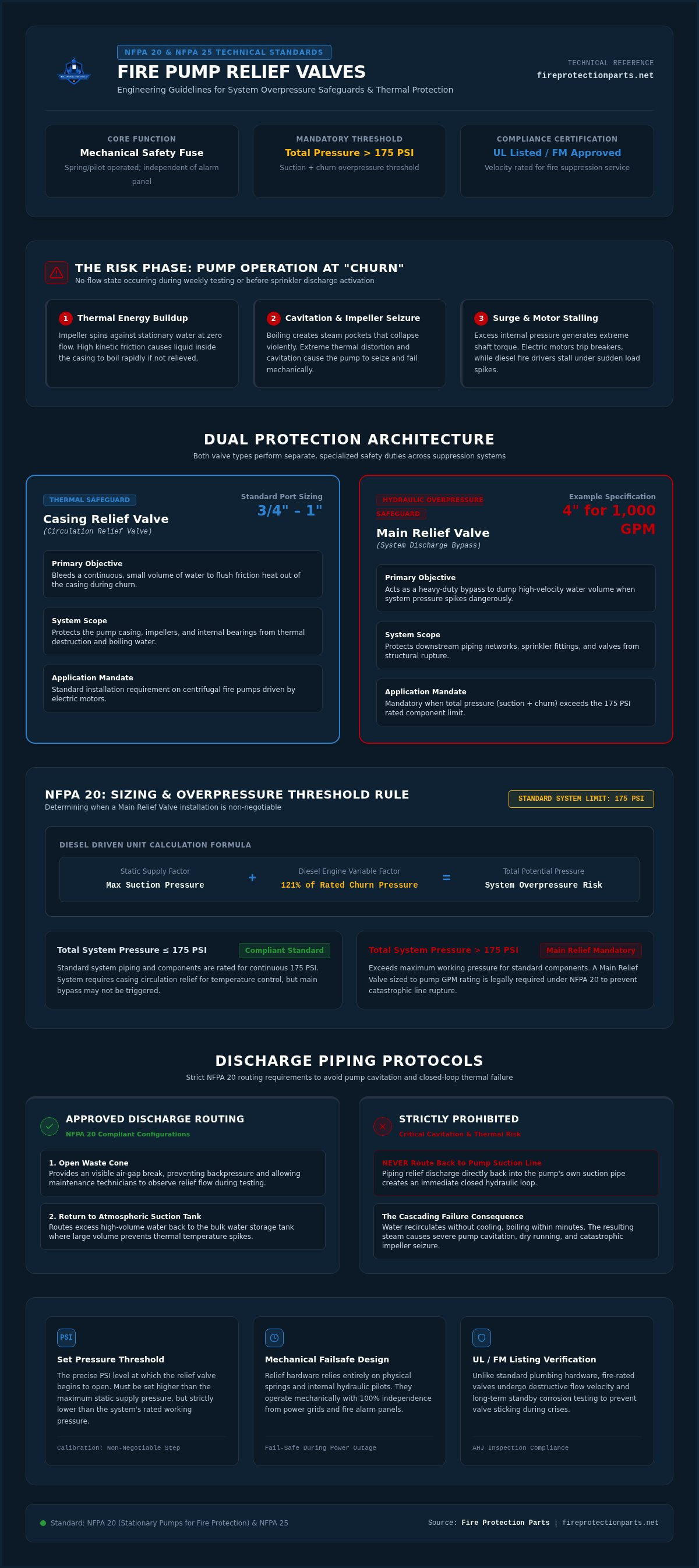
A fire pump relief valve functions as the mechanical safety fuse for your entire water-based fire protection system. It's designed to sense pressure spikes and react instantly. Unlike electronic sensors that can fail during a power outage, these valves rely on physical springs or pilots. This provides a fail-safe layer of protection that operates independently of the fire alarm control panel. Without it, the energy generated by a high-capacity pump has nowhere to go. This leads to broken pipes, damaged fittings, and system downtime when you can least afford it.
Fire pumps often run at "churn," which is a state where the pump operates but no water is flowing through the discharge piping. This occurs during weekly testing or when sprinklers haven't yet activated. During churn, the friction of the impeller spinning against stationary water generates immense heat. This is why stationary fire pumps and circulation relief valves are engineered to work in tandem. The valve bleeds off a small amount of water to keep the pump casing cool. If this heat isn't managed, the water can boil, causing the pump to cavitate and eventually seize.
Don't confuse these with standard plumbing valves. Fire-rated valves undergo rigorous UL/FM testing to ensure they won't stick or fail under extreme stress. They are built with materials that resist corrosion over decades of standby service. Standard plumbing hardware isn't designed to handle the specific flow velocities found in fire suppression. Using non-listed parts puts your entire facility at risk and will likely lead to a failed inspection from the Authority Having Jurisdiction (AHJ).
The Role of Relief Valves in Fire Suppression
These valves prevent catastrophic pipe bursts during the sudden surge of a pump start-up. They ensure that internal pressure stays within the safe design limits of your sprinkler system components online. Beyond protecting pipes, they safeguard the pump motor. Excessive pressure creates higher torque requirements, which can cause an electric motor to trip its breaker or a diesel engine to stall. A properly installed fire pump relief valve eliminates these risks by modulating pressure in real-time.
Essential Terminology: Set Pressure vs. Discharge Pressure
Understanding the "set pressure" is vital. This is the specific PSI threshold where the valve begins to open. It must be calibrated higher than your maximum static supply pressure but lower than the system's rated working pressure. "Churn pressure" is the maximum pressure the pump produces at zero flow. If your churn pressure plus your suction pressure exceeds 175 PSI, a main relief valve becomes a mandatory safety requirement. Accurate calibration isn't just a recommendation; it's a non-negotiable step for professional system safety.
Types of Fire Pump Relief Valves: Main vs. Casing Relief
Selecting the correct fire pump relief valve involves distinguishing between two vital functions: protecting the system piping and protecting the pump itself. While both manage pressure, they operate at different scales. A main relief valve acts as a heavy duty bypass for the entire discharge side, whereas a casing relief valve focuses solely on thermal regulation within the pump housing. High pressure systems often require a multi layered approach, using both valve types to eliminate the risk of catastrophic failure.
Main Relief Valves for High-Pressure Systems
A main relief valve is mandatory whenever the total pressure (maximum suction pressure plus 121% of the pump's rated churn pressure for diesel units) exceeds the pressure rating of the system components. For most standard setups, this threshold is 175 psi. These valves are sized based on the pump's Gallons Per Minute (GPM) rating. For example, a 1,000 GPM pump typically requires a 4 inch valve to handle the potential overflow. According to NFPA 20 standard requirements, the discharge must be piped to an open waste cone or back to an atmospheric suction tank. You should never pipe the discharge directly back into the pump suction line, as this creates a closed loop that rapidly overheats the water.
Casing Relief Valves: Small but Mighty
Casing relief valves, also known as circulation relief valves, are smaller components, usually 3/4 inch or 1 inch in size. They're standard on most centrifugal fire pumps driven by electric motors. Their job is simple: bleed off a small stream of water to prevent the pump casing from overheating during no flow conditions. Without this constant cooling, the water inside the pump will eventually boil, leading to seal failure or a seized impeller. These valves are equally critical in residential fire pump systems, where compact footprints make heat dissipation even more challenging. If your pump runs for its weekly test and you don't see a small stream of water from the casing relief, your system is at risk.
Longevity depends heavily on material selection. Stainless steel and bronze are the industry standards for a reason. These metals resist the corrosive effects of stagnant water and won't seize up after months of inactivity. Bronze is often preferred for its cost effectiveness in residential applications, while stainless steel provides superior strength for high pressure commercial environments. Ensure your system is fully protected by sourcing code-compliant relief valves from trusted experts who prioritize reliability above all else.
Understanding NFPA 20 Requirements for Relief Valves
Compliance with NFPA 20 is the baseline for any safe installation. For 2026, the industry follows the 2025 Edition of NFPA 20. It's not just about having a valve; it's about the specific configuration. For diesel engine-driven pumps, a fire pump relief valve is mandatory if 121% of the net rated churn pressure plus maximum static suction exceeds the system's working pressure. Electric pumps have different triggers, often revolving around Variable Frequency Drives (VFDs). If a VFD fails, the pump could run at full speed, creating an overpressure event that only a relief valve can mitigate.
NFPA 20 is strict about where that water goes. You can't just dump it anywhere. It must discharge to an open waste cone or an atmospheric tank. This provides a visible air gap. It allows operators to see the valve working during a test. More importantly, it prevents the thermal buildup discussed in previous sections. Closed-loop piping back to the suction line is a violation that leads to rapid cavitation and pump damage. Every installation must prioritize these discharge rules to remain code-compliant.
Sizing and Location Standards
Proper sizing is governed by NFPA 20 Table 4.28(a). You can't guess here. A 500 GPM pump needs a 3-inch valve, while a 2,500 GPM pump requires a 6-inch valve. Placement is equally critical. The valve must sit between the pump and the discharge check valve. This ensures it can protect the pump even if the downstream system is isolated. Ensure your layout allows for easy access to fire protection parts online for future repairs. Professional engineering involves specifying pressure-relief devices in fire systems that match the specific hydraulic profile of the building.
Testing and Certification Documentation
The Authority Having Jurisdiction (AHJ) will demand proof of UL Listing and FM Approval. UL 1478 is the standard for these valves. Without these stamps, your insurance carrier may deny coverage. Beyond the initial install, NFPA 25 (2026 Edition) requires annual flow testing. This test verifies the valve opens at the set point and closes drip-tight afterward. Always verify the pressure and temperature ratings on the manufacturer's nameplate before installation. This eliminates doubt and guarantees the hardware can handle the rigors of your specific environment.
Selection and Maintenance: Choosing the Right Relief Valve
Selecting a fire pump relief valve requires a methodical approach. It's not a component you can guess on. The selection process ensures your hardware matches the specific hydraulic realities of your building. Failure to calculate these values correctly leads to either unnecessary water discharge or, worse, a system rupture during a surge.
Start by calculating the maximum potential system pressure. You do this by adding the maximum static suction pressure from the city or tank supply to the pump’s churn pressure. If this total exceeds the rated working pressure of your system, typically 175 psi, a main relief valve is mandatory. While every centrifugal pump must have a casing relief valve for thermal protection, the main relief valve serves as the ultimate boundary for pipe safety. Ensure the valve body material is compatible with your environment. Cast iron is a durable choice for standard commercial pump rooms, while bronze is ideal for environments where moisture led corrosion is a constant threat.
Integration is the final selection step. You must verify that the valve and its discharge piping are compatible with your existing infrastructure. For instance, if you're using Viking CPVC fire sprinkler pipe, ensure the transition fittings and chemical properties of any lubricants or sealants are approved. This prevents stress cracking and ensures long term reliability.
Routine Maintenance for Relief Valves
Maintenance is the difference between a fail-safe system and a liability. Perform weekly visual inspections to check for leaks or signs of external corrosion. You should distinguish between a "weeping" valve and a "flowing" valve. A weeping valve drips slowly and usually indicates a need for cleaning or seal adjustment. A flowing valve suggests the set point has drifted or the seat is fouled by debris. Annually, NFPA 25 mandates a full trip test. During your annual pump flow test, verify the valve opens at the calibrated pressure and reseals tightly once pressure drops.
Common Failure Points to Watch For
Sediment buildup is the most frequent cause of reseating issues. Small particles of sand or rust can lodge in the valve seat, preventing a water tight seal. Spring fatigue also occurs over time. Constant tension can cause the internal spring to weaken, meaning the valve opens too early. In harsh or coastal environments, external corrosion can seize the pilot lines or the main stem. In these cases, upgrading to stainless steel internal components is a professional necessity to ensure the fire pump relief valve functions when called upon. Browse professional fire pump relief valves to find the right fit for your facility.
Sourcing Reliable Fire Pump Components Online
Sourcing a fire pump relief valve shouldn't be a gamble. In a high stakes industry where system failure isn't an option, the procurement process must be as reliable as the hardware itself. Choosing a specialized e-commerce retailer over a generic industrial supplier eliminates the risk of receiving parts that don't meet the rigorous demands of fire suppression. You need hardware that is specifically engineered, tested, and listed for fire protection service, not repurposed plumbing equipment that might fail under pressure.
Professional fire protection retailers understand the urgency of repairs. When a valve fails during an annual test, every day of downtime is a day the building remains unprotected. Fast shipping isn't just a convenience; it's a critical requirement for maintaining code compliance. By offering direct access to mission critical parts, specialized vendors help contractors and facility managers move quickly from identifying a problem to implementing a certified solution. Whether you're managing a single residential system or a large commercial pump room, the ability to source individual or bulk orders with confidence is essential.
Why Professional Assurance Matters
Code inspections are unforgiving. If an inspector finds a generic, non-listed valve where a UL/FM-listed fire pump relief valve is required, the system will be red-tagged immediately. Professional assurance means you receive verified hardware that carries the necessary certifications for insurance and legal compliance. Beyond the stamps on the metal, you gain access to expert support. Identifying the correct replacement part for an aging system can be complex. Having a partner who understands the technical nuances of pressure ratings and material compatibility provides the peace of mind that your suppression system remains fail-safe.
Your Partner in System Reliability
System integrity depends on a cohesive network of high quality components. Reliability starts with the pump but extends to every accessory, from air compressors for dry sprinkler systems to backflow preventers and seismic bracing. Fire Protection Parts serves as a dependable guide in this complex landscape, offering a comprehensive inventory that simplifies the procurement process. By centralizing your sourcing, you eliminate the logistical headaches of managing multiple vendors. This streamlined approach ensures that every part of your system, from the smallest casing relief valve to the largest deluge system, meets the same high standard of professional excellence.
Secure Your System with Professional Grade Protection
Maintaining a fail-safe fire suppression system requires more than just high-capacity hardware. It demands a precise understanding of how each component manages hydraulic stress. You now have the technical foundation to distinguish between thermal casing protection and large-scale overpressure relief. By adhering to the latest NFPA 20 standards and implementing a rigorous maintenance schedule, you eliminate the risks of pump seizure and pipe failure.
The right fire pump relief valve acts as the final line of defense for your facility. Don't leave your property's safety to chance with generic or unlisted parts. Professional-grade hardware ensures your system passes every inspection and performs flawlessly during a crisis. We provide the peace of mind you need through UL/FM-Listed Components, Expert Technical Support, and Fast Nationwide Shipping to keep your project on schedule.
Take the next step in safeguarding your infrastructure today. Shop Code-Compliant Fire Pump Relief Valves at Fire Protection Parts and build with the confidence of a seasoned professional.
Frequently Asked Questions
What is the difference between a casing relief valve and a main relief valve?
A casing relief valve is a small component designed to prevent the pump from overheating during no-flow conditions. It bleeds a small stream of water to cool the impeller. In contrast, a main fire pump relief valve is a larger device that protects the entire system from overpressurization. While the casing valve manages heat, the main relief valve prevents catastrophic pipe ruptures.
When is a main relief valve required for a fire pump according to NFPA 20?
NFPA 20 (2025 Edition) mandates a main relief valve for diesel pumps whenever the churn pressure plus maximum static suction exceeds the system's rated working pressure, usually 175 psi. It's also required for electric pumps equipped with Variable Frequency Drives (VFDs). This ensures that if the speed controller fails, the resulting pressure surge won't destroy downstream piping, fittings, or sprinkler heads.
Where should the relief valve discharge be piped?
Relief valve discharge must always be piped to an open waste cone or an atmospheric storage tank. This creates a visible air gap that allows operators to verify flow during testing. You must never pipe the discharge directly back into the pump's suction line. Doing so creates a closed loop that leads to rapid thermal buildup, causing the pump to cavitate and potentially seize within minutes.
How often should fire pump relief valves be tested?
Casing relief valves require inspection during the standard pump run test, which is weekly for diesel pumps and monthly for electric pumps. Main relief valves undergo a more rigorous annual trip test per NFPA 25 (2026 Edition). This annual flow test verifies that the valve opens at its specific set point and reseals tightly once the pressure returns to normal operating limits.
Can a fire pump operate without a relief valve?
Technically, a constant-speed electric pump can operate without a main fire pump relief valve if the total churn pressure remains below the system's 175 psi rating. However, all centrifugal fire pumps require a casing relief valve to prevent thermal damage. Operating without these essential safety boundaries voids your UL/FM listings and places your facility at significant risk of mechanical failure during a fire event.
What happens if a fire pump relief valve is set too high?
If the valve's set point exceeds the rated working pressure of your system components, the valve won't open during a pressure surge. This defeats its purpose as a safety fuse. The resulting hydraulic stress can cause pipe bursts, joint failures, or damage to delicate sprinkler components. Accurate calibration is vital to ensure the valve modulates pressure before it reaches dangerous, non-compliant levels.
Do residential fire pump systems require relief valves?
Yes, residential fire pump systems require relief valves to maintain safety and code compliance. Most residential setups utilize a casing relief valve to protect the pump during testing. If the pump's boost pressure plus the street pressure can exceed the rating of your CPVC piping, a main relief valve is also necessary. These components ensure that residential systems remain as reliable as their commercial counterparts.
How do I size a relief valve for a 750 GPM fire pump?
According to NFPA 20 Table 4.28(a), a 750 GPM fire pump requires a relief valve with a minimum nominal size of 3 inches or 4 inches. The associated discharge piping must be sized even larger, typically 5 inches or 6 inches, to minimize friction loss. Professional sizing ensures the valve can handle the full flow capacity of the pump without creating excessive backpressure in the system.

